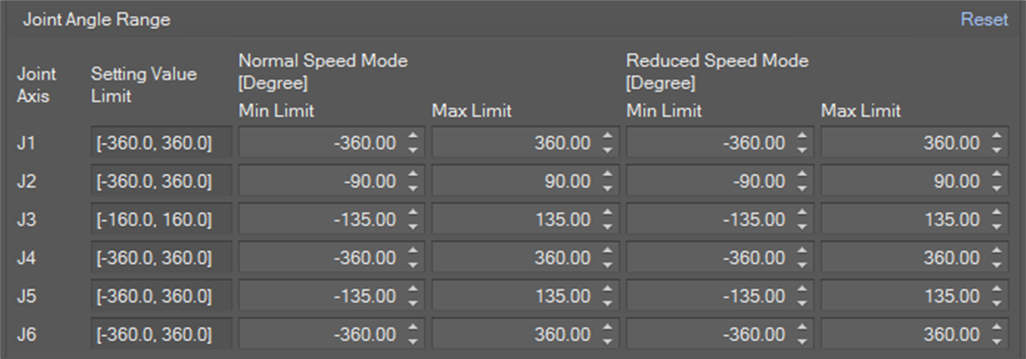
Joint Limit
-
Joint Angle Range: This is a limit for joint angle by degree. If the angle of an axis exceeds the limit, a JOINT_SLP violation error is invoked.
-
Joint Speed: This is a limit for joint speed by degree/sec. If the speed of an axis exceeds the limit, a JOINT_SLS violation error is invoked.
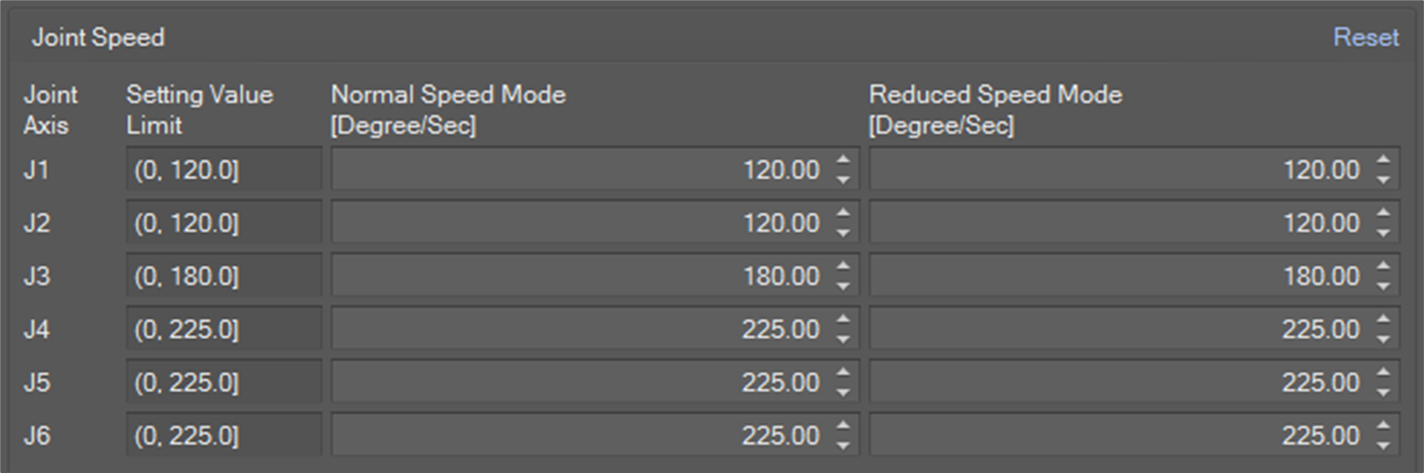
You need to set the limits for Normal Speed Mode and Reduced Speed Mode. Normal speed mode limit is applied when the system is in a state of Manual operation, Hand-guiding operation or Stand-alone autonomous operation. In contrast, Reduced Speed Mode limit is applied when the system is in a state of Collaborative autonomous operation.
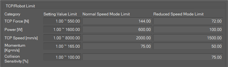
TCP/Robot Limit
-
TCP Force: It is a limit for force on TCP in N. If the force on TCP exceeds the limit, a TCP_SLF violation error is invoked.
-
Power: It is a limit for power on TCP in W. If the power exceeds the limit, TCP_POWER violation error is invoked.
-
TCP Speed: It is a limit for TCP speed in mm/sec. If the TCP speed exceeds the limit, TCP_SLS violation error is invoked.
-
Momentum: It is a limit for TCP momentum in Kg∙m/sec. If the momentum exceeds the limit, TCP_MOMENTUM violation error is invoked.
-
Collision sensitivity: It is a criterion for collision detection in percent units. The higher the value, the smaller the external force the robot stops with. If a collision is detected, a COLLISION violation error is invoked.
If the Collision detection mute zone is configured and TCP is inside a collision detection mute zone, the collision sensitivity for the zone is applied.
You need to set the limits for Normal speed mode and Reduced Speed Mode. Normal speed mode limit is applied when the system is in a state of Manual operation, Hand-guiding operation or Stand-alone autonomous operation. In contrast, Reduced Speed Mode limit is applied when the system is in a state of Collaborative autonomous operation.
Safety Stop Mode
You can assign a stop mode for each safety violation.
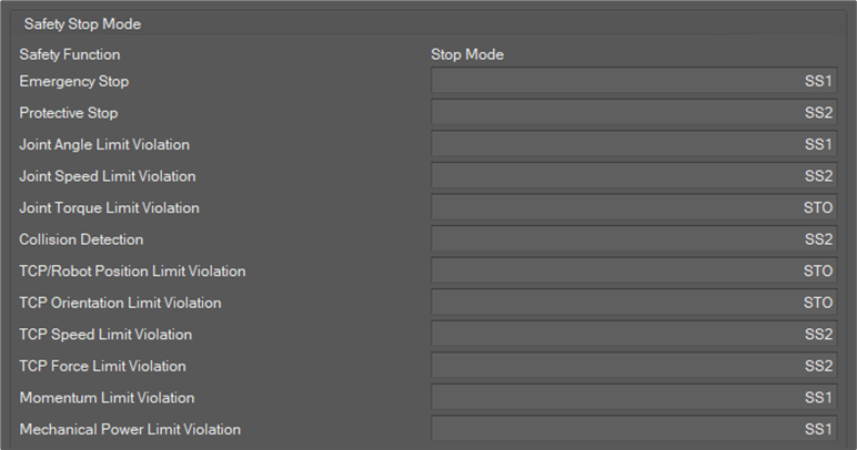
There are four kinds of stop modes.
-
STO: Cuts off the motor power immediately.
-
SS1: Cuts off the motor power after motion stop.
-
SS2: Holds position after motion stop
-
RS1: Reactive stop after collision. It can only be applied for a Collision violation.
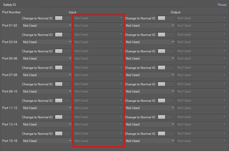
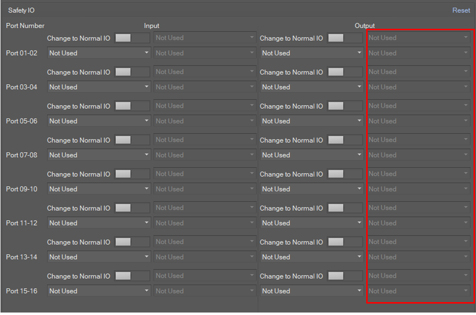
Safety IO - Safety Input
Safety Input defines robot action when the corresponding signal is invoked.
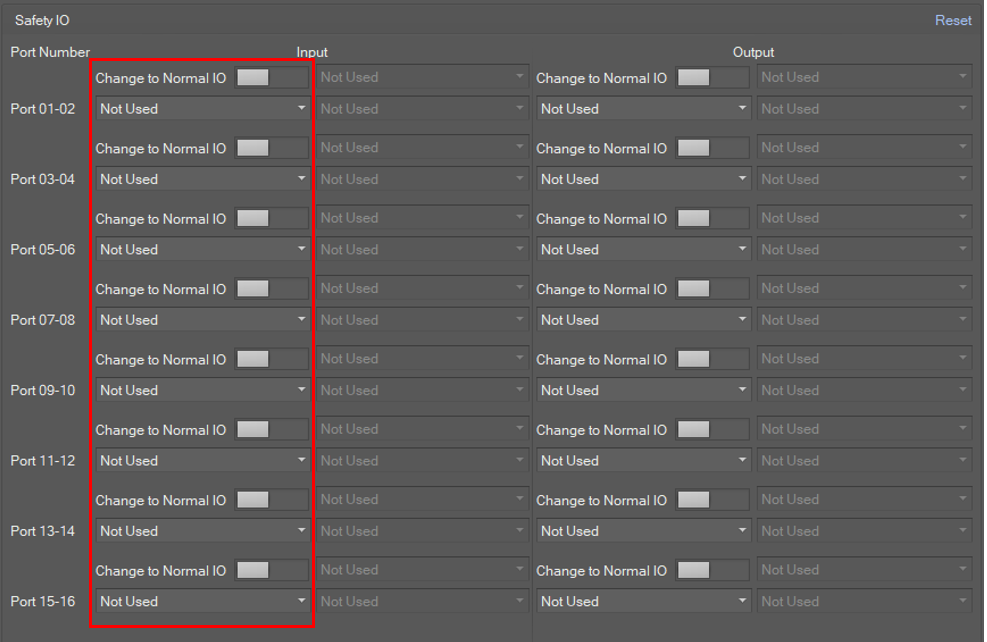
Possible options are as below.
|
0 |
Not Used |
|
1 |
Emergency Stop (L) |
|
2 |
Emergency Stop - No Loopback (L) |
|
3 |
Protective Stop (L) |
|
4 |
Protective Stop - STO (L) |
|
5 |
Protective Stop - SS1 (L) |
|
6 |
Protective Stop - SS2 (L) |
|
7 |
Protective Stop (L) - Auto Reset & Resume (R) |
|
8 |
Interlock Reset (R) |
|
9 |
Reduced Speed Activation (L) |
|
10 |
3-Pos Enable Switch (H) |
|
11 |
Handguiding Enable Switch (H) |
|
12 |
Remote Control Enable (H) |
|
13 |
Safety Zone Dynamic Enable (H) |
|
14 |
Safety Zone Dynamic Enable (L) |
|
15 |
HGC End & Task Resume (R) |
Safety IO - Normal Input
Safety input can be switched to normal input.
A signal is invoked for the corresponding normal input port when the configured normal input action occurs.
Possible options are as below.
|
0 |
Not Used |
|
1 |
Power On (H) |
|
2 |
Power Off (H) |
Safety IO - Safety Output
A signal is invoked for the corresponding safety output channel when the configured safety output action occurs.
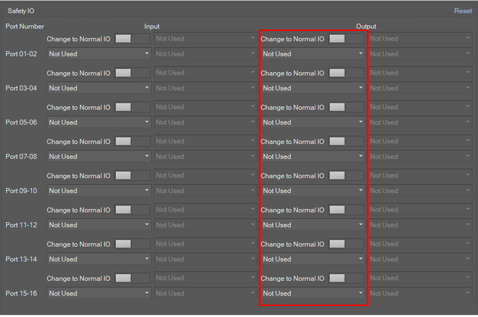
Possible options are as below.
|
0 |
Not Used |
|
1 |
Emergency Stop (L) |
|
2 |
Emergency Stop - excl. No Loopback Input (L) |
|
3 |
Safe Torque Off (L) |
|
4 |
Safe Operating Stop (L) |
|
5 |
Abnormal (L) |
|
6 |
Normal Speed (L) |
|
7 |
Reduced Speed (L) |
|
8 |
Auto Mode (L) |
|
9 |
Manual Mode (L) |
|
10 |
Remote Control Mode (L) |
|
11 |
Standalone Zone (L) |
|
12 |
Collaborative Zone (L) |
|
13 |
High Priority Zone (L) |
|
14 |
Tool Orientation Limit Zone (L) |
|
15 |
Designated Zone (L) |
Safety IO - Normal Output
Safety output can be switched to normal output.
A signal is invoked for the corresponding normal output port when the configured normal output action occurs.
Possible options are as below.
|
0 |
Not Used |
|
1 |
Safe Torque Off (L) |
|
2 |
Safe Operating Stop (L) |
|
3 |
Normal Speed (L) |
|
4 |
Reduced Speed (L) |
|
5 |
Auto Mode (L) |
|
6 |
Manual Mode (L) |
|
7 |
Remote Control Mode (L) |
|
8 |
Standalone Zone (L) |
|
9 |
Collaborative Zone (L) |
|
10 |
High Priority Zone (L) |
|
11 |
Tool Orientation Limit Zone (L) |
|
12 |
Designated Zone (L) |
|
13 |
Task Operating (L) |
|
14 |
Robot In Motion (L) |
|
15 |
Mastering Alarm (L) |
|
16 |
Home Position (L) |
|
17 |
Deceleration - SS1 SS2 (L) |
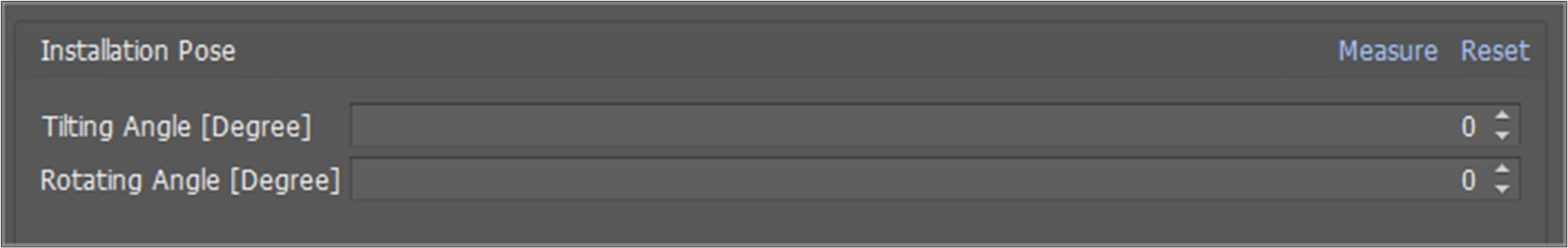
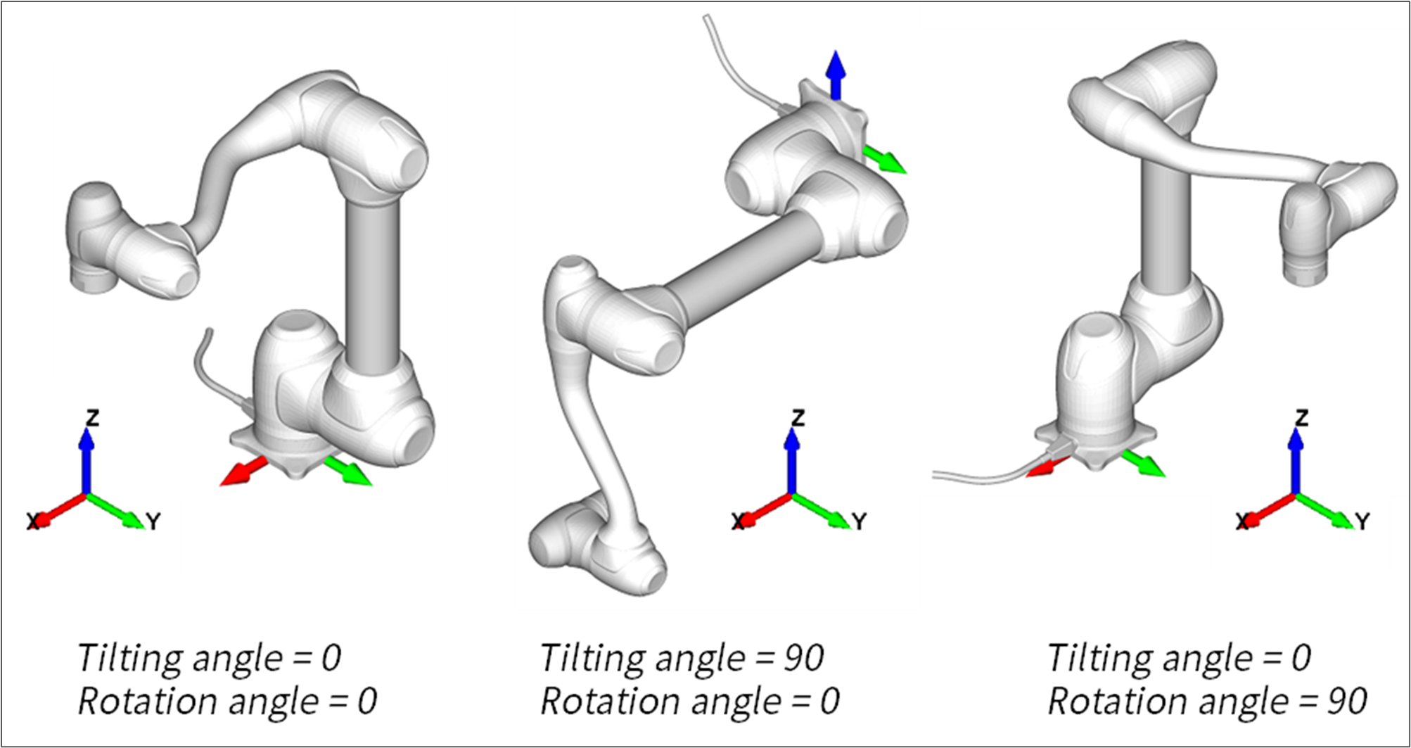
Installation Pose
When the robot is mounted on a side wall or ceiling, you must set the install pose.
-
Tilting Angle: Tilting angle in degrees between the ground and the robot base frame.
-
Rotation Angle: Rotation angle along vertical axis.
Cockpit Button
It provides the editing function to set the teaching mode of the cockpit button.
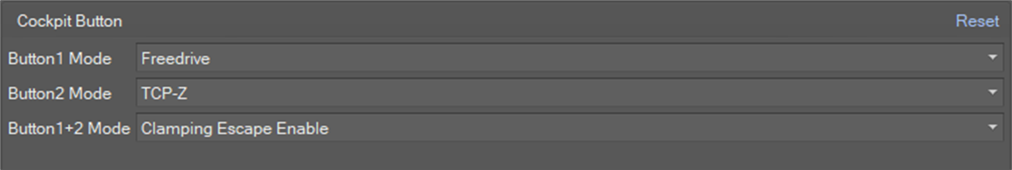
Teaching mode is as follows.
-
TCP-Z
-
TCP-XY
-
Orientation Only
-
Position Only
To use the clamping escape function, select Clamping Escape Enale in Button1+2 mode.
Speed Reduction Rate
It provides the editing function to set the following property items.
|
Item |
Range |
Unit |
|
CWS Speed Reduction Rate |
1~100 |
% |
|
IO Speed Reduction Rate |
1 ~100 |
% |
Nudge
It provides the editing function to set the following property items for Nudge.
|
Item |
Range |
Unit |
|
Input Force |
10~50 |
N |
|
Delay Time |
0 ~30 |
Sec |
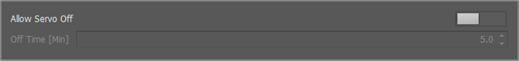
Idle Servo Off
Idle Servo Off is one of our system’s safety policies. If the robot is not used for more than 5 minutes, it will cut off the servo power. If not, turn off the Allow Servo Off button.
To only change the servo off time, set the Off Time value.