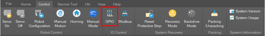
To monitor or set the IO of the controller and the robot arm flange, select Control on the main menu and click the GPIO button.
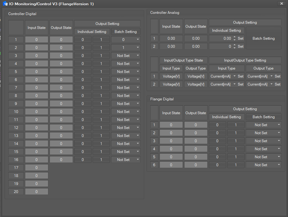
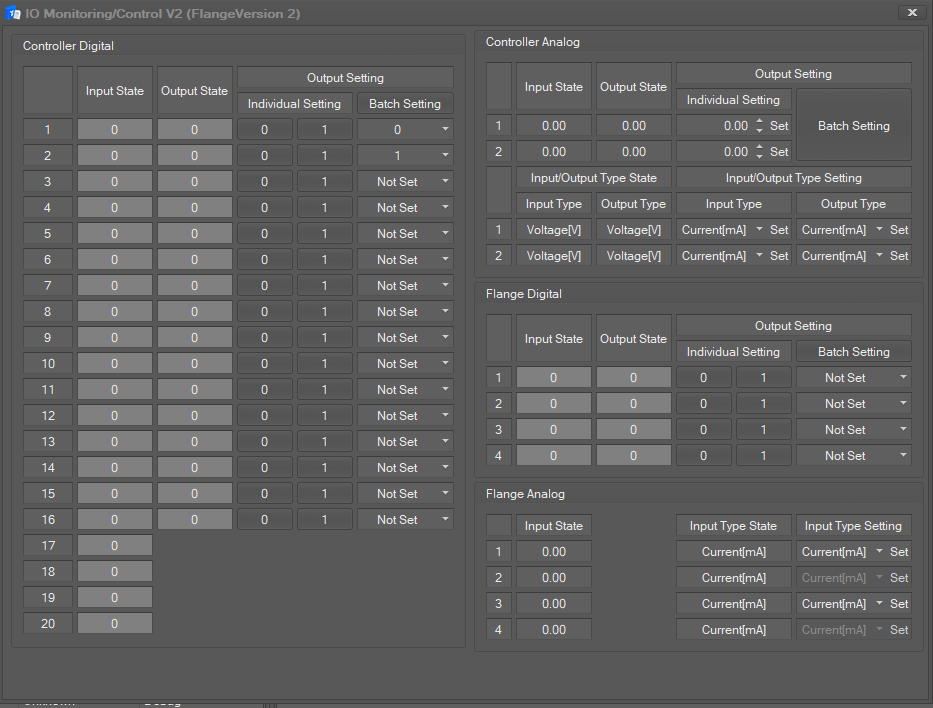
The IO Monitoring / Control window is composed of three parts: Controller Digital/Analog setting and Flange Digital/Analog Setting.
-
Flange Version 1
-
Flange Version 2
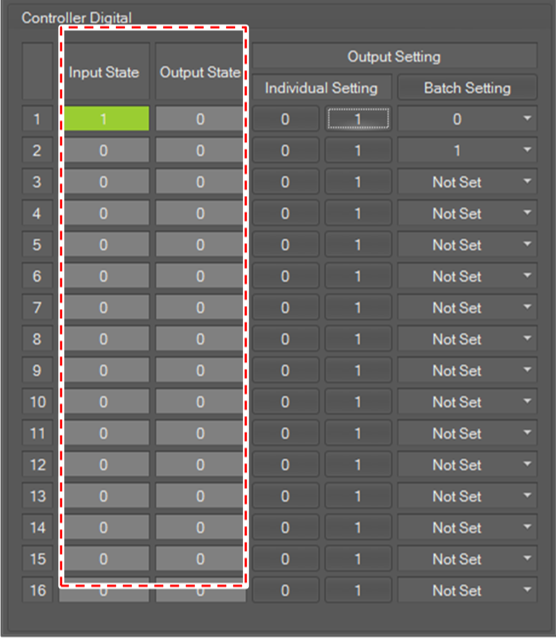
Controller Digital
The Digital IO state of the controller is displayed in the Input State/Output State field.
-
If the signal is high, the IO state color is displayed in green.
-
If the signal is low, the IO state color is displayed in gray.
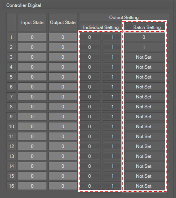
To set output, click the 0 or 1 button for each channel in Individual Setting.
To set all outputs at once, set the desired value in each channel at the bottom of the Batch Setting button and click the Batch Setting button.
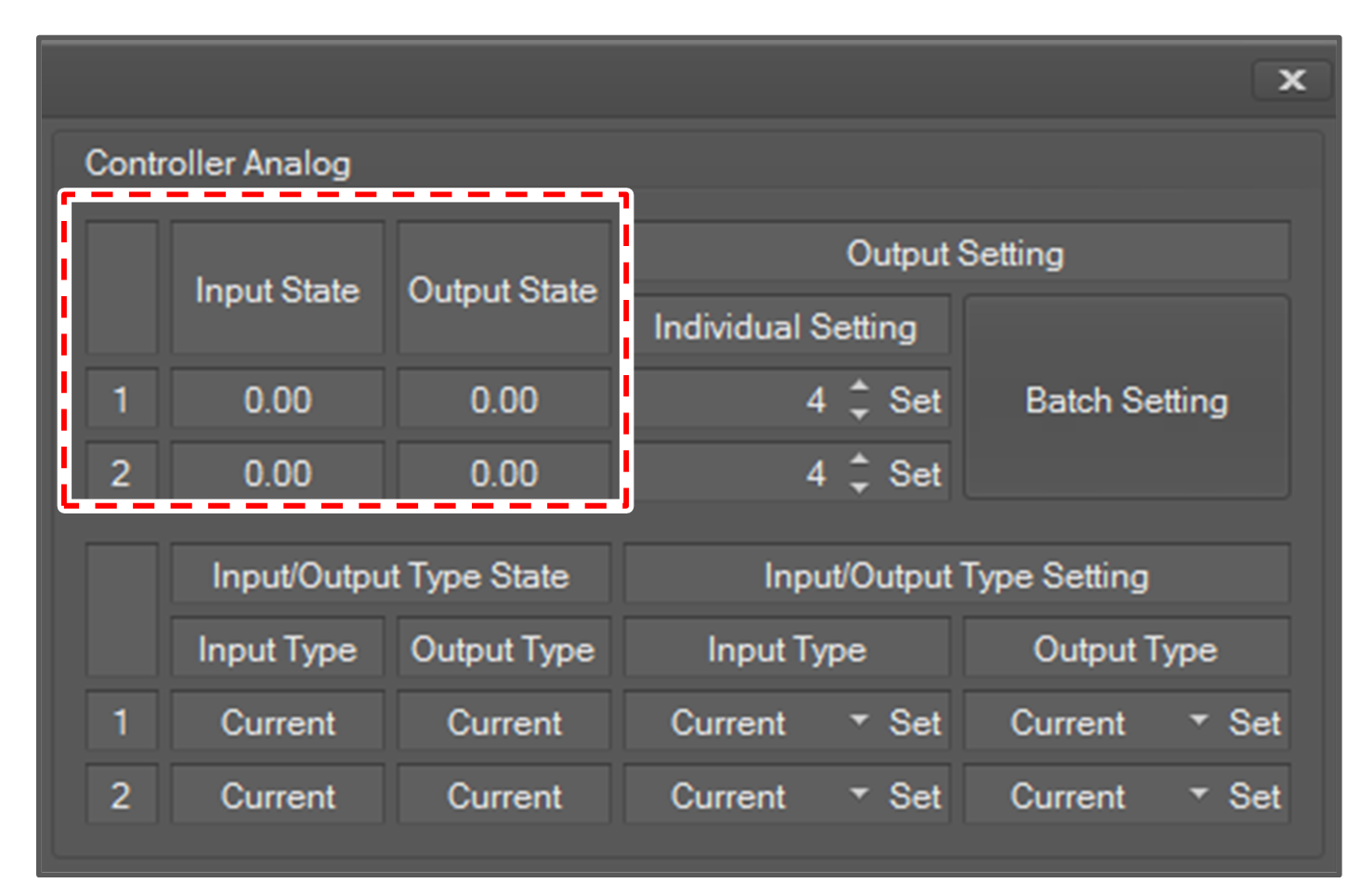
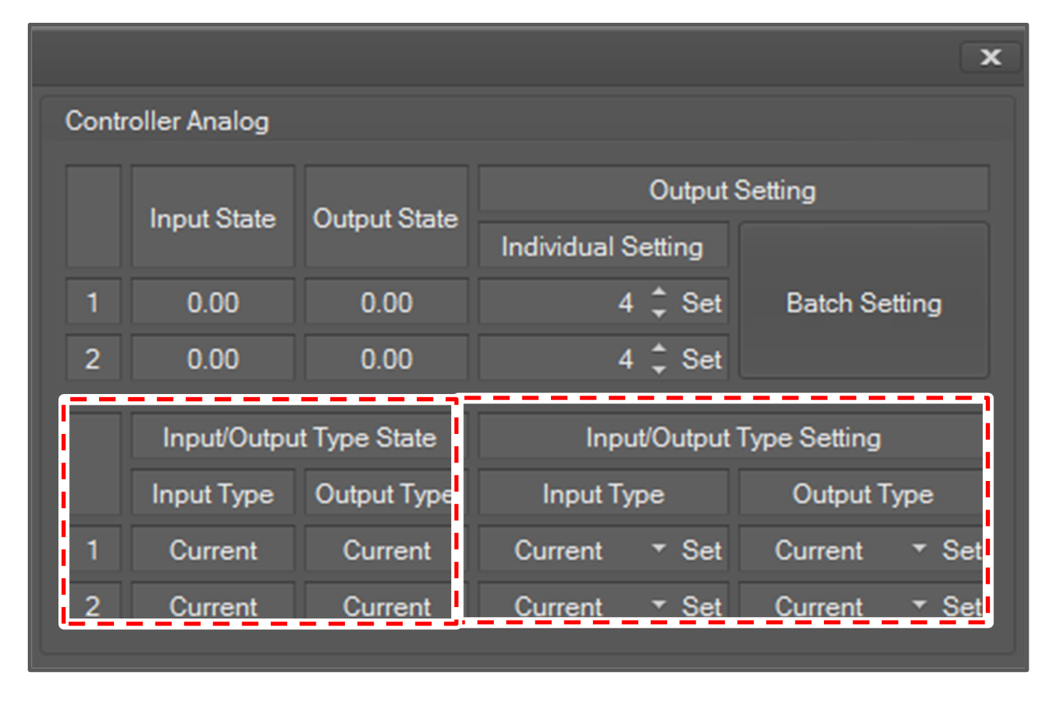
Controller Analog
The Analog IO state of the controller is displayed in the Input State/Output State field
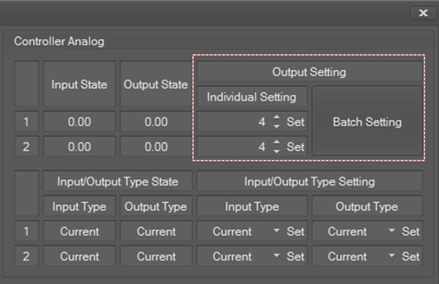
To set output, set Output Setting and click the corresponding Set button.
To set all output values at once, set the analog output fields and click the Batch Setting button.
Controller Analog Value Type Setting
The analog input/output type state of the controller is displayed in the Input/Output Type State field.
You can set the value type of analog input and output. It can be current or voltage.
To set the value type, select the type and click the Set button for the input/output type that you want to set in Input/Output Type Setting.
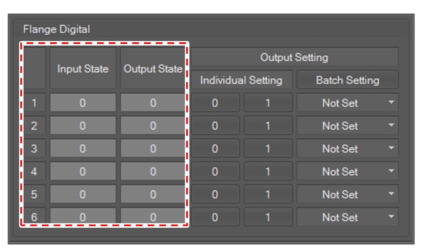
Flange Digital
The Digital IO state of the flange is displayed in the Input State, Output State field. As with the Controller Digital, the IO state color is green if the signal is high and gray if the signal is low.
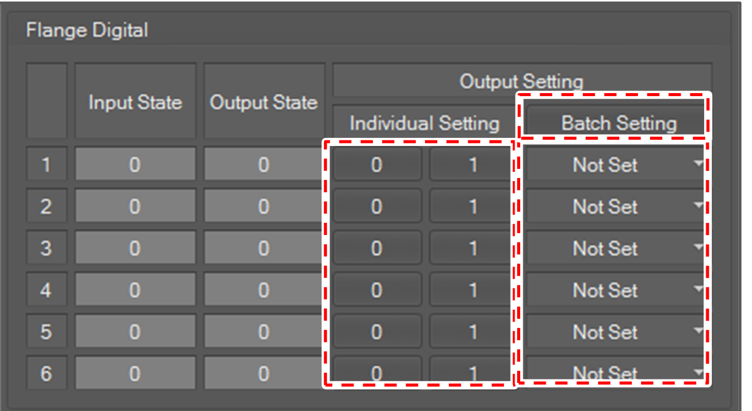
To set output, click the 0 or 1 button in Individual Setting.
To set all outputs at once, select value for the flange digital and click the Batch Setting button.
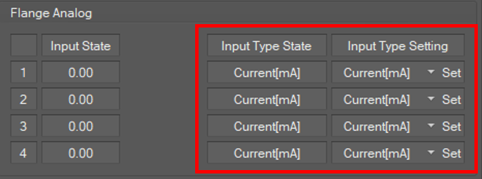
Flange Analog
There is no analog output from the flange. Input is expressed as a real number.
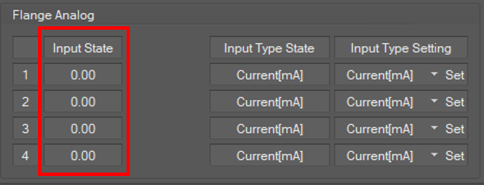
Flange Analog Value Type Setting
The analog input type state of the flange is displayed in the InputType State field.
You can set the value type of analog input. It can be current or voltage.
To set the value type, select the type and click the Set button for the inputtype that you want to set in Input Type Setting.