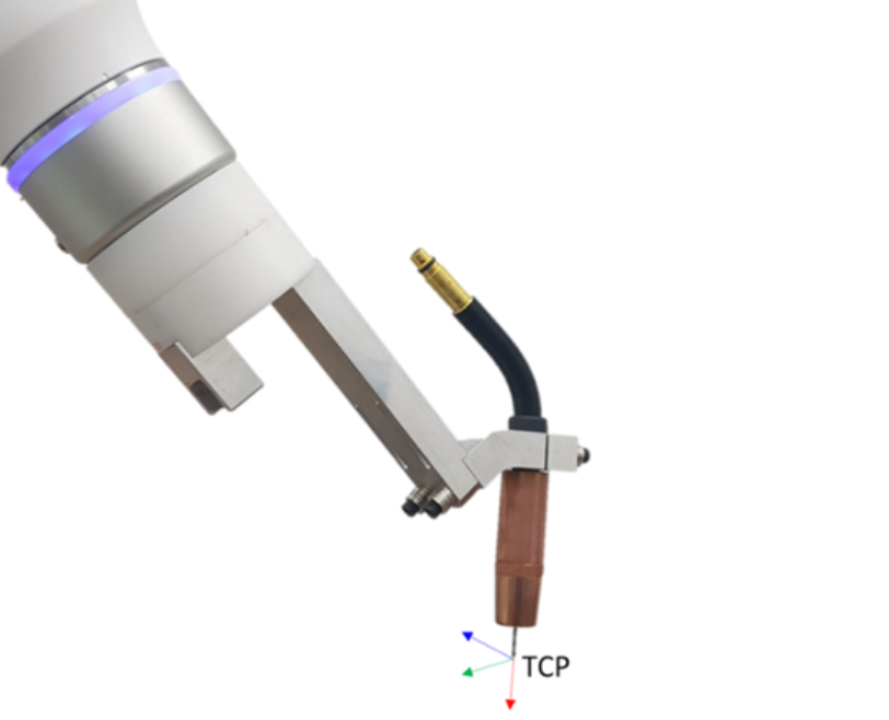
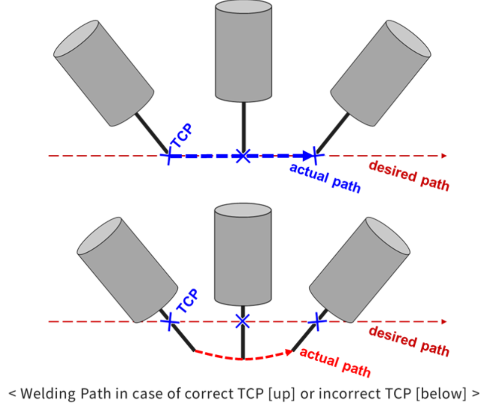
For welding that linear work using on the wire end of the welding torch, it is critical to enter accurate TCP information for the welding torch. The TCP pose during welding must be entered taking into account distance from the welding torch to the wire feed length (stick-out). Refer to the figure below.
Caution
After setting the welding torch information, the torch TCP set in the “Tool Center Point (TCP)” menu in the Robot Parameters module must be applied to be finally reflected in the robot’s position, and is not automatically reflected by just the welding torch setting. Since the estimated welding torch TCP is not automatically reflected, when teaching welding work, the welding torch set before teaching must be selected and reflected.
1. TCP Calculation
Whenever the torch has been re-installed or the wire stick-out changed, it is recommended that you manage the consistency of TCM mechanically by using the TCP management jig to prevent inconsistency between the set TCP value and the actual wire end position. However, if it is difficult to accurately identify the TCP according to the changed torch and wire stick-out, TCP calculation can be used to easily make adjustments. The TCP pose and angle are calculated, and the manual calculation function can be used when necessary.
2. TCP Pose Calculation Function
Maintaining a constant wire discharge amount, take four different postures centered on a fixed point and record them as Pose 1 to Pose 4. At this time, it is recommended to prepare a probe fixed around it and use it as a fixed point.
Finally, when you press the TCP Calculation button, the estimated TCP position will appear in the Position-X/Y/Z/A/B/C items. You can adjust the length in the Z-axis direction based on the TCP coordinate system from the estimated TCP position through the “Stick Out” item.
To reflect the adjustment, press the TCP Calculation button, and the recalculated TCP position will appear in the Position-X/Y/Z/A/B/C items. If you do not utilize the TCP angle estimation function, you must additionally enter the TCP angle (A, B, C) values.
3. TCP Pose Orientation Calculation Function
After completing the CP position estimation process, activate the “Use direction calculation” item. After removing the nozzle, keep the wire discharge amount constant and take four different poses centered on a fixed point, and then record them in Pose1 to Pose4 respectively.
At this time, it is recommended to prepare a fixed probe in the surrounding area and use it as a fixed point. Finally, when you press the TCP Calculation button, the estimated TCP position and direction will appear in the Position-X/Y/Z/A/B/C items.
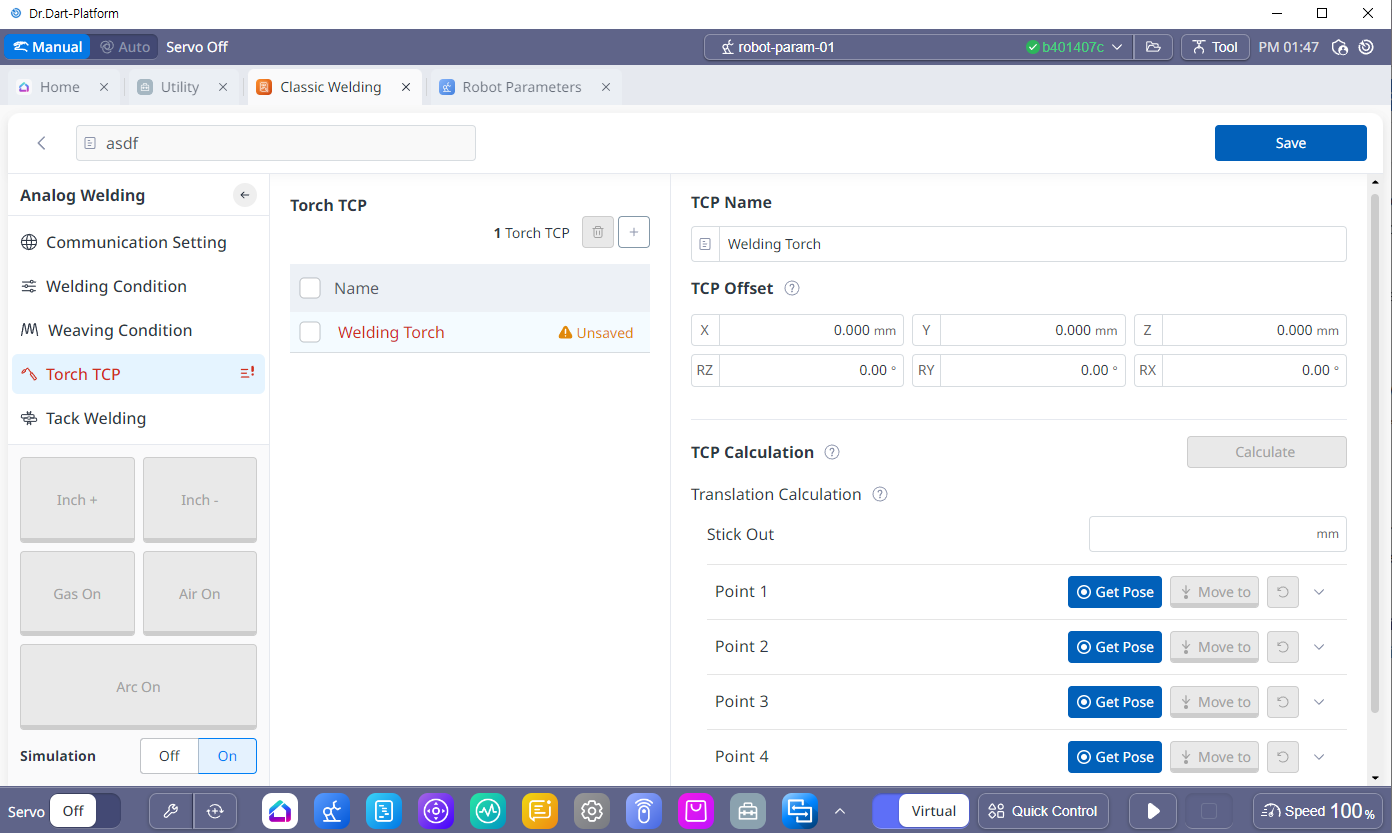
4. Welding Torch Setting Screen
|
No |
Category |
Desc |
|---|---|---|
|
1 |
TCP Name |
This is the TCP name applied to the actual Robot. It may be different from the Torch name, and you can check whether it is registered in the Robot Parameters module → Tool Center Point (TCP). Warning When registering TCP, if it is registered as “Unsaved” as shown in the screen above, the TCP is not registered. In order to use it, you must register the TCP through the “Save” button. |
|
2 |
TCP Offset |
TCP coordinates for the torch connected to the robot. This is also where the results are displayed when automatically calculating TCP. |
|
3 |
TCP Calculation |
Stick Out, TCP Position Calculation When selecting the Calculate 4-Points and Orientation option, enter an additional 4-point point and press the button to estimate the position and orientation of the TCP (if the option is selected) and display the results. |
|
4 |
Stick Out |
Enter the length of the discharged wire |
|
5 |
Use Orientation Calculation |
After selecting an option, you can enter four additional teaching points to automatically calculate the direction of the TCP. |