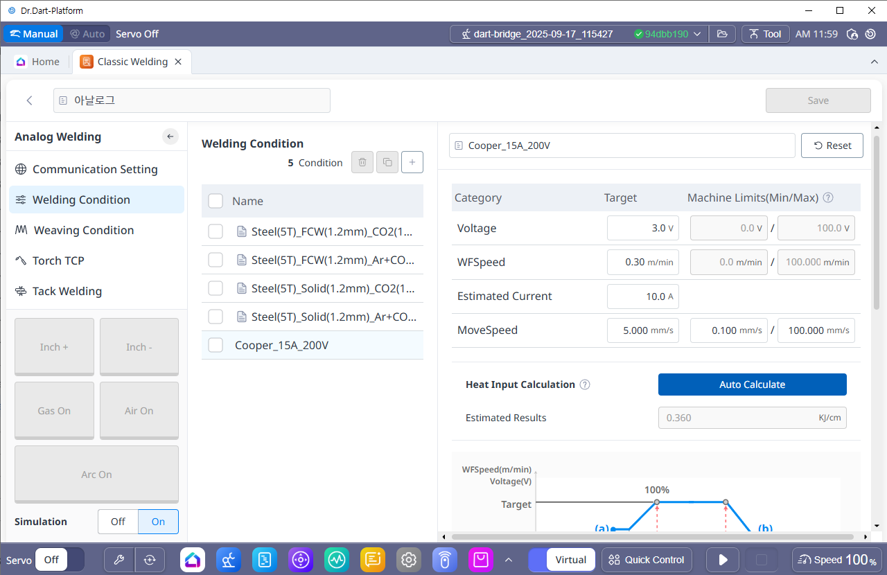
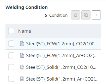
After completing the welding machine settings, you can set the welding conditions, create new welding conditions, or modify/delete existing welding conditions. You can also check all welding conditions in a list format, and copy existing welding conditions and set them as new conditions.
There are basic welding conditions and user-created welding conditions. You can use the basic welding conditions as they are or add new welding conditions based on the basic welding conditions.
1. Welding Condition Basic Setting
-
Default Welding Condition
-
The welding conditions provided by default allow you to perform a welding program with the conditions or copy it with a different name and modify it. Deletion is not possible, and in the case of analog welding machines, four basic conditions are provided.
-
-
Custom Welding Condition
-
Welding conditions created by the user using the basic welding settings. They can be modified, duplicated, and deleted.
-
2. Welding Condition Detail Setting
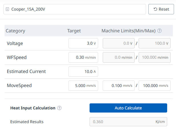
You can set the target voltage, target feed rate, target speed, and detailed welding process variables, which are the basic conditions for welding operations. The Welding Machine has already been set in the previous step, and the target conditions are limited to the minimum/maximum output values of the welding machine.
-
Welding conditions can be set by voltage, feed speed, expected current, and travel speed. MIG/MAG welding uses a constant voltage type welder, so if the target voltage is constant, the output voltage of the welding machine is also constant.
-
The output current of the welding machine varies depending on various conditions such as the welding voltage, material of the base metal, feeding speed, material, type, and discharge length of the welding wire.
-
In order to monitor the welding current during welding, you must connect the current monitoring channel of the welder or a separately installed current sensor to check.
-
Please note that the Programming command uses mm/sec as the motion speed input.
|
No. |
Category |
Desc |
|---|---|---|
|
1 |
Voltage |
Enter the voltage output command of the welder within the maximum/minimum range (V). |
|
2 |
WFSpeed |
Enter the wire feed speed command within the maximum/minimum range (m/min). |
|
3 |
Estimated Current |
Enter the current expected to occur at the set target voltage and feed rate command. The input value is only used for heat input calculation and is not reflected in the actual welding conditions. |
|
4 |
MoveSpeed |
Enter the robot's movement speed during welding. The unit is cm/min. (0.100~100.000mm/sec) |
|
5 |
Heat Input Calculation |
There are cases where heat input is managed in welding work. Press the Auto Calculation button to calculate and display the expected heat input based on the currently set voltage, expected current, and speed conditions. The relationship between voltage, current, and heat input is as follows.
|
|
No |
Categoey |
Desc |
|---|---|---|
|
1 |
Start-End WFSpeed (%) |
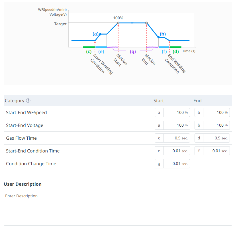
Set the ratio of the start delivery speed to the end delivery speed based on the target delivery speed (100%) value. (0~200%) |
|
2 |
Start-End Voltage(%) |
Set the ratio of the start voltage and end voltage based on the target voltage (100%) value. (0~200%) |
|
3 |
Gas Flow Time |
Sets the time of shielding gas discharge before welding initial wire feeding / after welding end wire feeding. (You can input 0 or more and 2.00 or less) |
|
4 |
Start-End Condition Time |
Set the time for the start and end conditions. (You can enter between 0 and 2.00.) |
|
5 |
Condition Change Time |
Enter the change time to smoothly change the target value from the current command to the next command when the welding condition command is changed. (You can enter 0 or more and 2.00 or less.) |
|
6 |
User Description |
You can enter any additional description you need. |
3. Basic Sequence of Welding Process
-
The basic sequence of the welding process, which defines the flow of various signals from the start to the end of welding, is as follows (1) to (8). Please refer to the graph below.
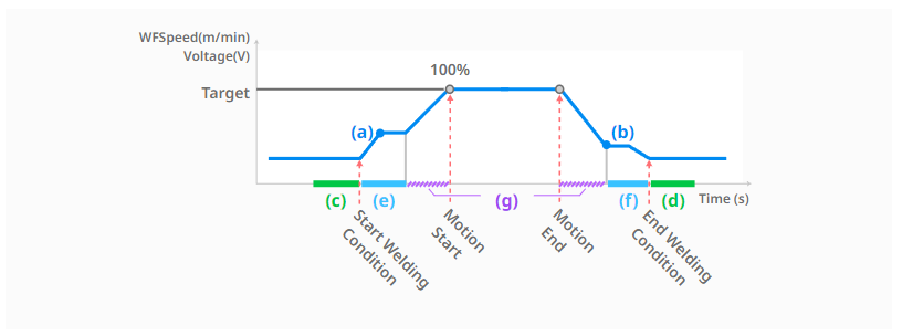
(1) Motion command authorization for welding operation [Start welding]
: The welding process starts. For information on welding operations, command configuration, and execution, see ‘Welding Programming (TaskEditor)’ and ‘Welding Monitoring’.
(2) Protective gas release phase [during gas flow time-start, corresponding to section (c)]
: This is the first step to release the protective gas to prevent oxidation during welding. Enter the gas flow rate and time.
(3) Welding initial condition stage [start end condition time-start, corresponding to section (e)]
: After the protective gas discharge step, welding is started by applying the voltage/feed speed. If the feed speed/voltage is applied at the beginning of welding without going through the welding initial condition step, the welding condition may be unstable and the arc may not occur. The ratio of the target feed speed value in the welding initial condition step and the target feed speed of this welding condition can be determined as the start-end feed speed value-start. The ratio of the target voltage value and the target voltage of this welding condition can be determined as the start-end voltage-start.
(4) This welding section (target condition) transition step [target condition reached after welding condition change time, corresponding to section (g)]
: After the initial condition step, the welding conditions are adjusted to the target conditions. The welding conditions are gradually changed during the welding condition change time.
(5) Motion start and main condition maintenance stage [possible through welding condition adjustment popup]
: After this welding section transition step, the motion starts and the set target conditions are maintained. In this step, you can change the welding conditions of voltage/feed speed/speed using the real-time welding condition adjustment pop-up window. Even when changing the welding conditions in real time, the welding condition change time is applied, so the welding conditions gradually change over the set time.
(6) Motion end and welding end condition transition stage [After welding condition change time, reaching the end feed speed value, corresponding to section (g)]
: When the motion is finished, the welding condition gradually changes from the target condition to the end condition during the welding condition change time. The ratio of the target feed speed value at the welding end condition change step to the target feed speed of the main welding condition can be determined as start-end feed speed value-end. The ratio of the target voltage value to the target voltage of the main welding condition can be determined as start-end voltage-end.
(7) Welding end condition step [start-end condition time-end, corresponding to section (f)]
: Change the welding conditions to be initialized during the start-end condition time-end after the welding end condition transition step.
(8) Protective gas release phase [during gas flow time-end, corresponding to section (d)]
: After the welding end condition stage, the target voltage/feed speed becomes 0 and the digital output corresponding to Arc-On is also turned off. This is the stage where the protective gas that prevents oxidation during welding is discharged to the end. Enter the gas flow rate time-end value.