Tool Center Point
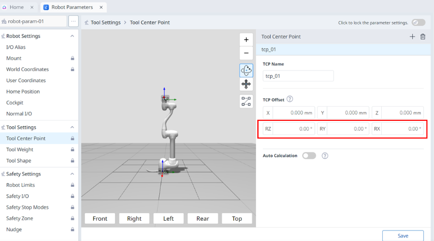
-
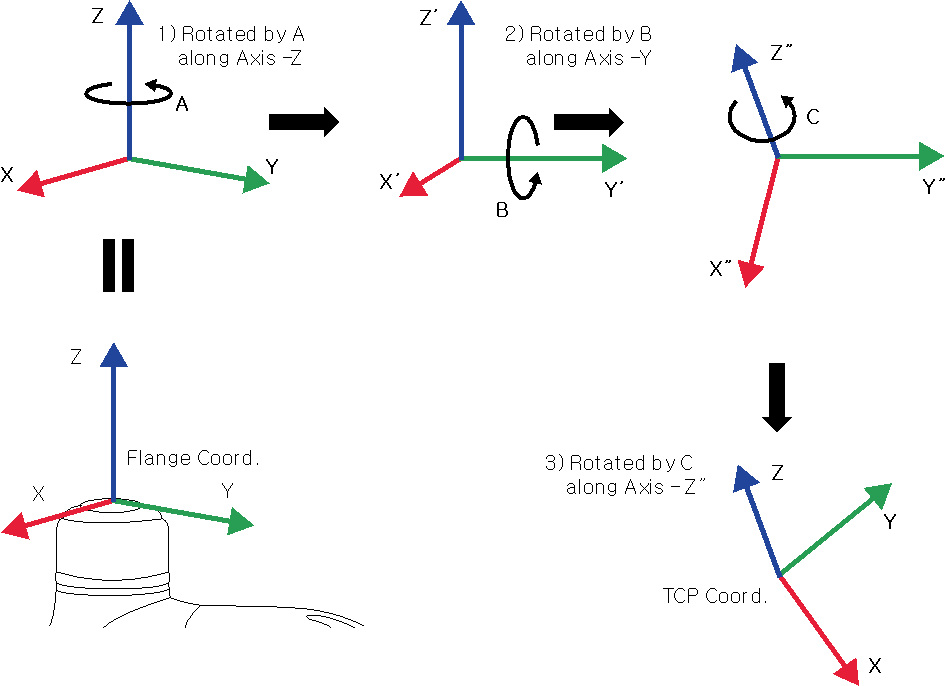
Rotate A degrees along the z axis of the flange coordinate.
-
Rotate B degrees along the y’ axis of the coordinate rotated according to 1).
-
Rotate C degrees along the z’’ axis of the coordinate rotated according to 2).
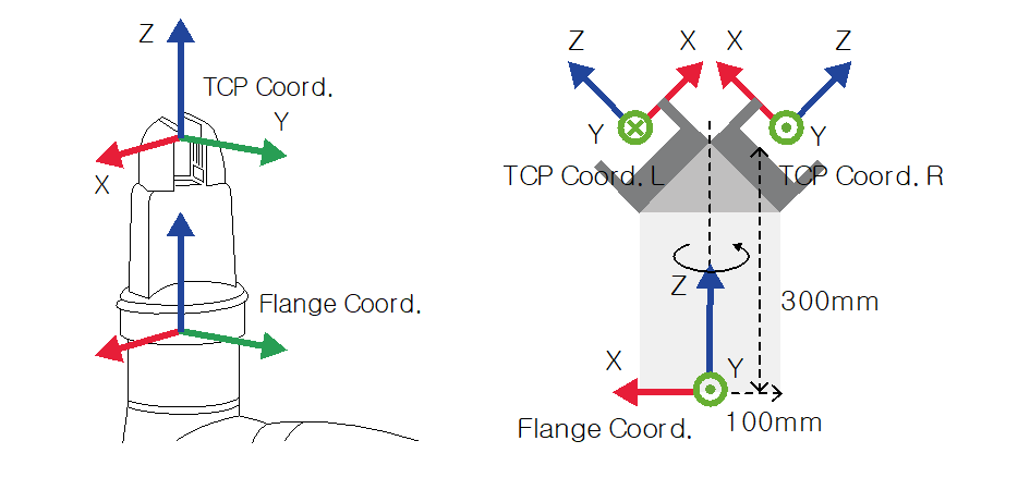
Here are a few examples of configuring the TCP according to the method described above:
Unknown Attachment
|
|
|
|
|---|---|---|
|
1 |
Lock toggle button |
|
|
2 |
3D Simulation |
This is where you can simulate the configured Tool Center Point. |
|
3 |
Adding |
This button allows you to add TCP. |
|
4 |
Deleting |
This button allows you to delete the selected TCP. |
|
5 |
Save |
This button allows the setting values to be saved. |
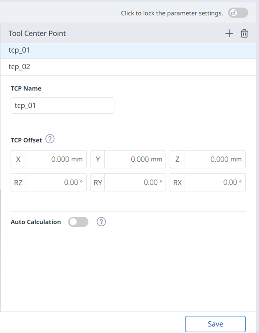
When the settings are locked, the screen below is seen.
Unknown Attachment
At this time, the selected TCP is seen in blue as shown below.
Tool Weight
-
The tool weight can be measured using the auto measure function.
-
-
The activated tool weight Item can be set as the standard tool weight by pressing the set tool icon ( ![]()
-
Up to fifty different tool weights can be registered.
-
In the case of M series, acceleration automatically adjustment function when the maximum tool weight exceeds the maximum tool weight.
Unknown Attachment
Unknown Attachment
|
|
|
|
|---|---|---|
|
1 |
Lock toggle button |
|
|
2 |
Adding |
This button allows you to add a new Tool Weight. |
|
3 |
Deleting |
This button allows you to delete a Tool Weight. |
|
4 |
Tool Weight List |
A list of the configured Tool Weights. |
|
5 |
Tool Weight Name |
This is where you can enter a name for the Tool Weight. |
|
6 |
Auto Measure Motion |
This button allows you to run the automatic measurement. |
|
7 |
Automatic Measurement |
This button allows you to select an option and run an automatic measurement for it. |
|
8 |
Motion Selection |
You can select the desired Motion from the options. |
|
9 |
Selection of the Use of Weight |
You can choose whether to use weight. This selection box is disabled for E Series or A Series without FPT sensors. |
|
10 |
Weight Input |
This is where you can enter the desired weight. |
|
11 |
Selection of the Use of Center of Gravity CX |
The use of the center of gravity CX can be selected. |
|
12 |
CX Input |
CX can be entered. |
|
13 |
Selection of the Use of Center of Gravity CY |
The use of the center of gravity CY can be selected. |
|
14 |
CY Input |
CY can be entered. |
|
15 |
Selection of the Use of Center of Gravity CZ |
The use of the center of gravity CZ can be selected. |
|
16 |
CZ Input |
CZ can be entered. |
|
17 |
Whether to Use Inertia |
This checkbox allows you to choose whether to use inertia. |
|
18 |
lxx Input |
An lxx entry for inertia can be entered. |
|
19 |
lyy Input |
An lyy entry for inertia can be entered. |
|
20 |
lzz Input |
An lzz entry for inertia can be entered. |
|
21 |
lxy Input |
An lxy entry for inertia can be entered. |
|
22 |
lyz Input |
An lyz entry for inertia can be entered. |
|
23 |
lzx Input |
An lzx entry for inertia can be entered. |
|
24 |
Save |
This button allows you to save the setting values. |
Tool Shape
The shape of the tool installed on the flange can be set by adding a tool shape.
-
-
Take caution as the zone the robot can maneuver will decrease if the tool shape is set too large.
Up to fifty different tool shapes can be registered.
Unknown Attachment
|
|
|
|
|---|---|---|
|
1 |
Lock toggle button |
|
|
2 |
3D Simulation |
This is where you can 3D Simulate the result of the configured Tool Shape. |
|
3 |
Tool Shape Name |
The name of the configured Tool. |
|
4 |
Tool Shape Form |
The shape of the configured Tool. |
|
5 |
Editing Tool Shape |
This button allows you to edit the configured Tool Shape. |
|
6 |
Deleting Tool Shape |
This button allows you to delete the selected Tool Shape. |
|
7 |
Adding Tool Shape |
A tool shape can be added. |
|
8 |
Applying |
This button allows you to apply the Tool Shape after setting it. |
Unknown Attachment
|
|
|
|
|---|---|---|
|
1 |
Tool Shape |
This indicates that this pane is a Tool Shape pop-up. |
|
2 |
Entering a Name |
This is a field where the name of the Tool Shape can be entered. |
|
3 |
Cautionary Message |
A note of caution when setting up |
|
4 |
Add New Cuboid |
This button allows you to add a cuboid. |
|
5 |
Add New Sphere |
This button allows you to add a sphere. |
|
6 |
Add New Capsule |
This button allows you to add a capsule. |
|
7 |
Cancel |
This button allows you to cancel the setting. |
|
8 |
Confirm |
This button allows you to confirm the setting. |
Once the cube/sphere/capsule is added, the display is seen as below.
|
Unknown Attachment |
Unknown Attachment |
|
Unknown Attachment |
|