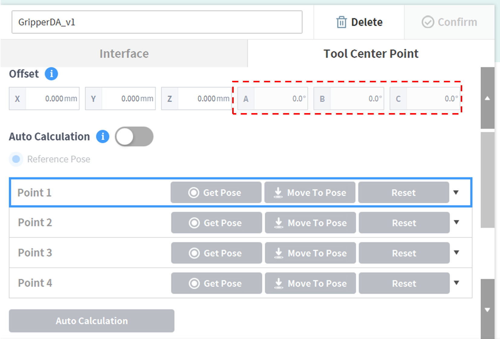
When configuring the tool center point (TCP), the position and rotation angle based on the flange coordinates must also be defined. At this time, The distance from the default starting point of the flange coordinate to the toolcenter point (TCP) inthe X, Y and Z directions cannot be set to be greater than 10000 mm. Also, note that Force Control, Compliance 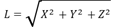
If the tool center point (TCP) is configured using Auto Calculate, the calculation is made based only on the X, Y and Z positions, so it is necessary to enter the rotation angle. The rotation angle can be defined with RZ, RY, and RX and it based on the “Euler Z-Y-Z” rotation method.
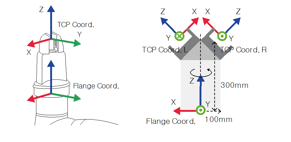
The definitions of the coordinate axis expressed with x, y, z and coordinate axis expressed with X, Y, Z are as follows:
-
Coordinate axis of “Flange Coordinate” (x, y, z): The coordinate axis direction of the “flange coordinate ”defined at the end of the flange is identical to the robot coordinate when the robot joint angle of the robot is (0,0,0,0,0,0).
-
Coordinate axis of the “TCP Coordinate” (X, Y, Z): This is set at the end or at the working point of the tool installed on the end of the flange. At this time, the rotation angle of the “TCP Coordinate” is defined based on the “Flange Coordinate”in the order of 1) to 3) of the following:
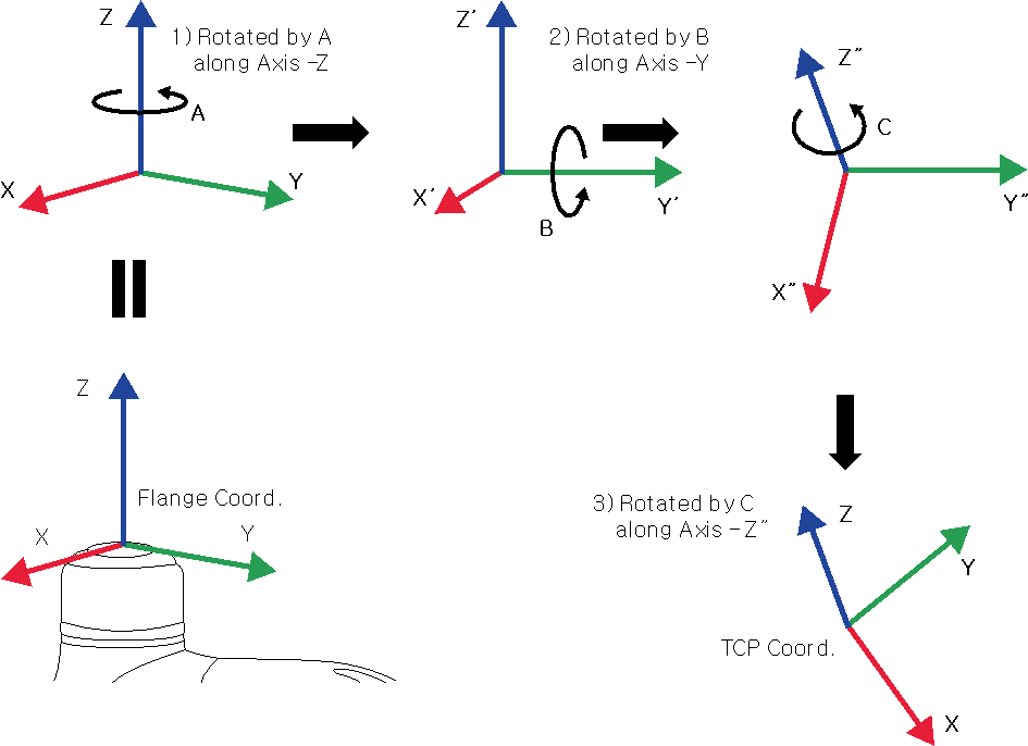
1) Rotate A degrees along the z axis of the flange coordinate.
2) Rotate B degrees along the y’ axis of the coordinate rotated according to 1).
3) Rotate C degrees along the z’’axis of the coordinate rotated according to 2).
Here are a few examples of configuring the TCP according to the method described above:
-
[X, Y, Z, A, B, C] = [0, 0, 100, 0, 0, 0]: General Gripper with only a Z-direction offset (TCP Coord)
-
[X, Y, Z, A, B, C] = [100, 0, 300, 180, -45, 0]: Left Gripper with 45-degree angle (TCP Coord. L)
-
[X, Y, Z, A, B, C] = [-100, 0, 300, 0, -45, 0]: Right Gripper with 45-degree angle (TCP Coord. R)
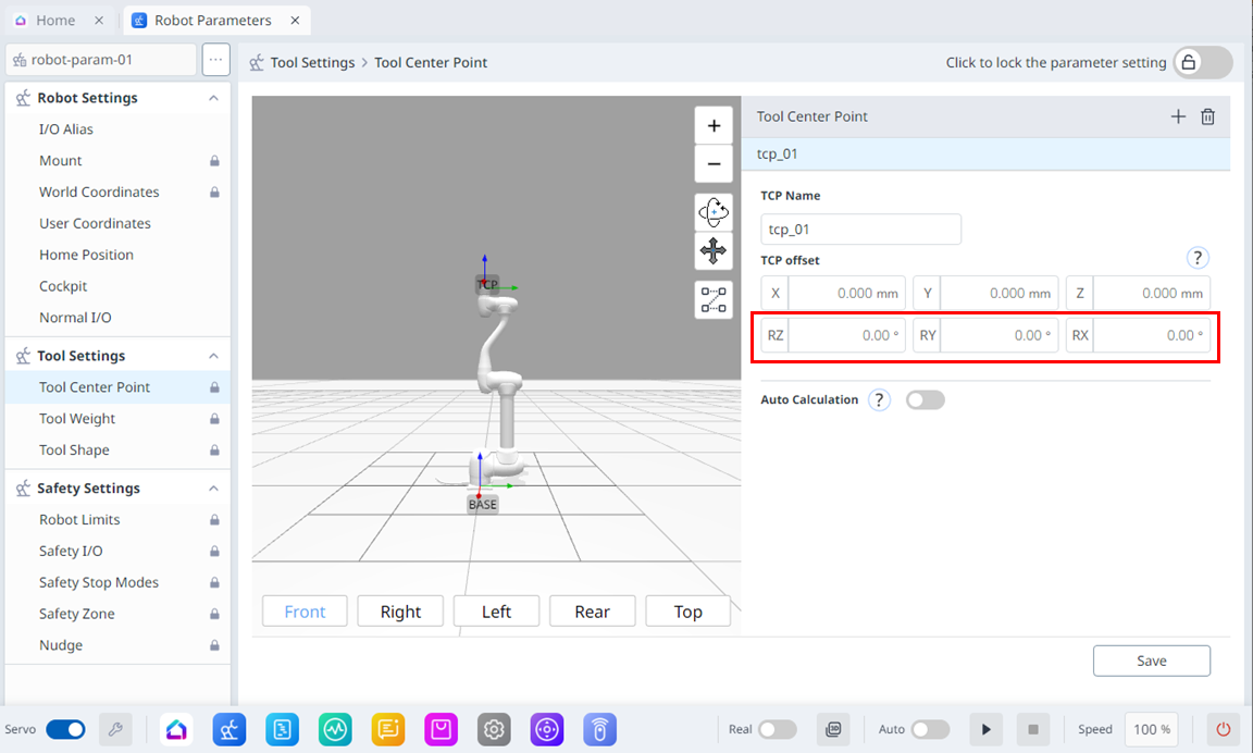
|
|
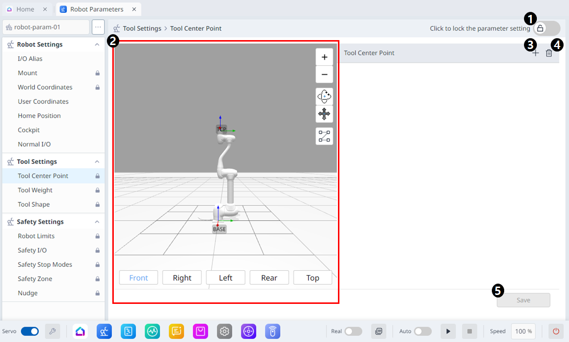
Item |
Description |
|---|---|---|
|
1 |
Lock Toggle Button |
Used to lock the set value. The safety password is required for modifying the value. |
|
2 |
3D Simulation |
This is where you can simulate the configured Tool Center Point. |
|
3 |
Adding |
This button allows you to add TCP. |
|
4 |
Deleting |
This button allows you to delete the selected TCP. |
|
5 |
Save |
This button allows the setting values to be saved. |
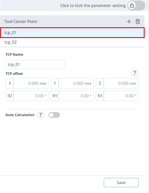
When the settings are locked, the screen below is seen.
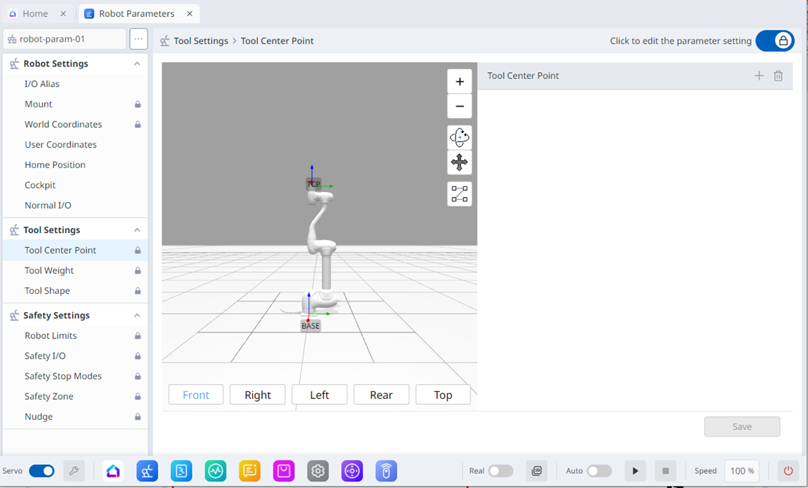
At this time, the selected TCP is seen in blue as shown below.