Power-up controller
MANDATORY EASY 3 MIN
In case of the A Series, the system can be powered up only after the emergency stop button setting switch is configured. For more information, refer to Emergency Stop Button Setting Switch.
- In case of the A Series, the teach pendant is not powered up if the emergency stop setting switch is not configured or if the there is an emergency I/O signal input on Safety I/O .
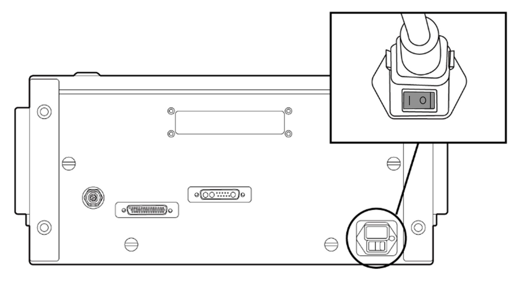
The power switch of the controller is located at the bottom of the controller.
Press the power switch at the bottom of the controller. The system is powered up including robot, controller, teach pendant and smart pendant.
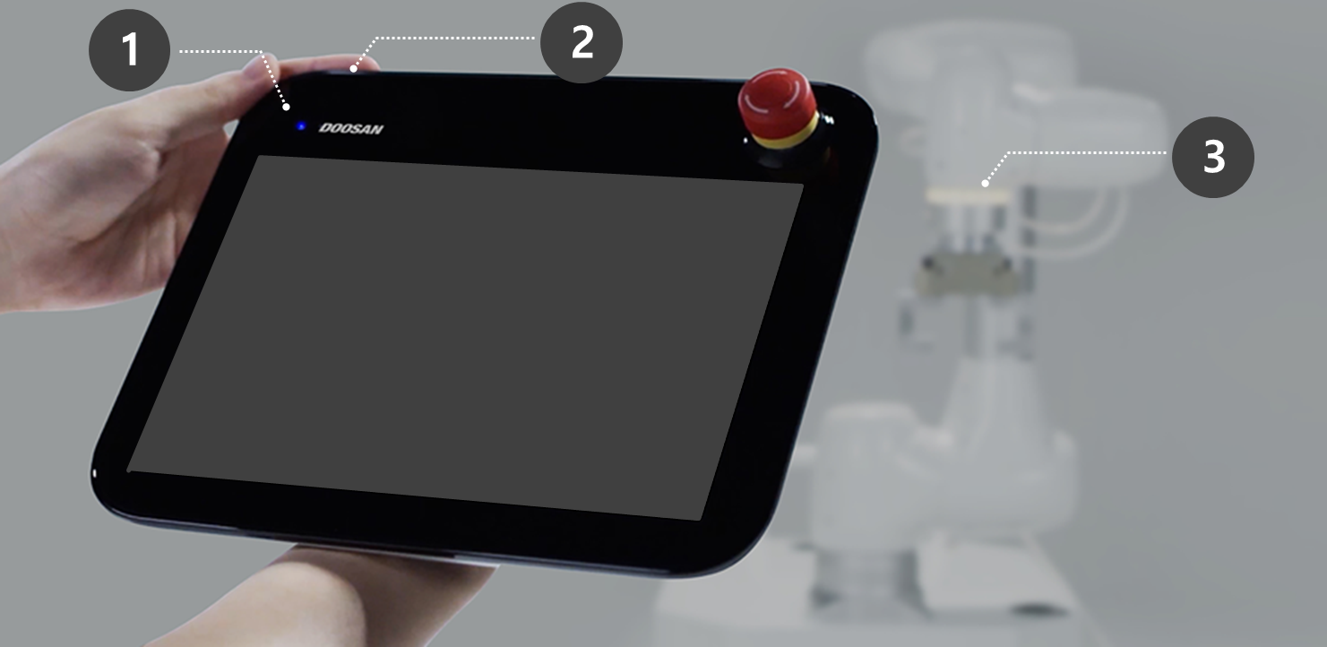
- Press and hold the power button (Fig. 2) until the teach pendant screen powers up. The teach pendant LED (Fig. 1) and flange LED (Fig. 3) will blink red until the robot controller connects to the network.
- For more information about equipment other than the teach pendant, refer to System Power On/Off.
Note
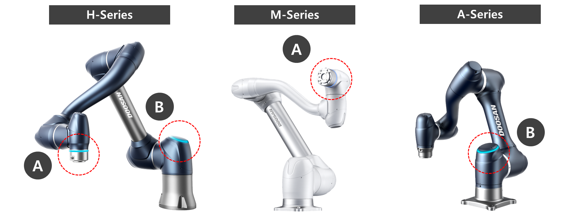
LED positions of each Doosan Robotics robot series are as follows:
- A: Flange LED
- B: Axis 1 LED