
Tool Settings
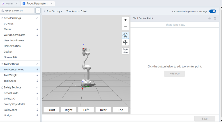
Tool Center Point
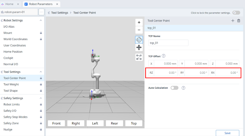
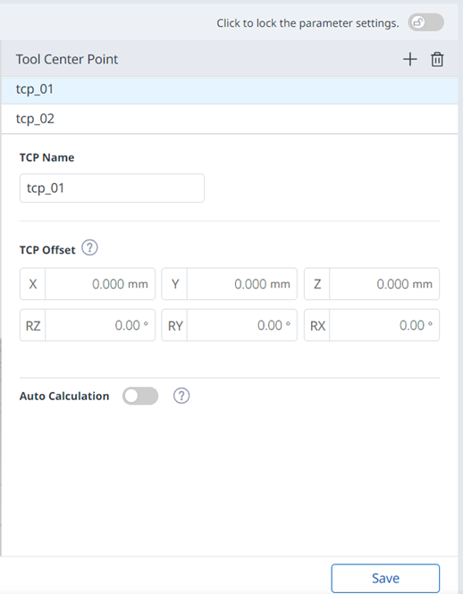
When configuring the tool center point (TCP), the position and rotation angle based on the flange coordinates must also be defined. ime, The distance from the default starting point of the flange coordinate to the toolcenter point (TCP) inthe X, Y and Z directions cannot be set to be greater than 10000 mm. Also, note that Force Control, Compliance Control, and Direct Teaching-Point Fixation are only available when the converted lengths of X, Y, and Z (![]() ) are 300 mm or shorter.
) are 300 mm or shorter.
If the tool center point (TCP) is configured using Auto Calculate, the calculation is made based only on the X, Y and Z positions, so it is necessary to enter the rotation angle. The rotation angle can be defined with RZ, RY, and RX and it based on the “Euler Z-Y-Z” rotation method.
The definitions of the coordinate axis expressed with x, y, z and coordinate axis expressed with X, Y, Z are as follows:
Coordinate axis of “Flange Coordinate” (x, y, z): The coordinate axis direction of the “flange coordinate ”defined at the end of the flange is identical to the robot coordinate when the robot joint angle of the robot is (0,0,0,0,0,0).
Coordinate axis of the “TCP Coordinate” (X, Y, Z): This is set at the end or at the working point of the tool installed on the end of the flange. At this time, the rotation angle of the “TCP Coordinate” is defined based on the “Flange Coordinate” in the order of 1) to 3) of the following:
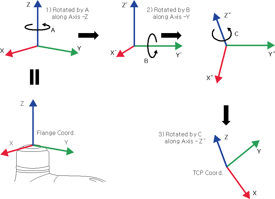
Rotate A degrees along the z axis of the flange coordinate.
Rotate B degrees along the y’ axis of the coordinate rotated according to 1).
Rotate C degrees along the z’’ axis of the coordinate rotated according to 2).
Here are a few examples of configuring the TCP according to the method described above:
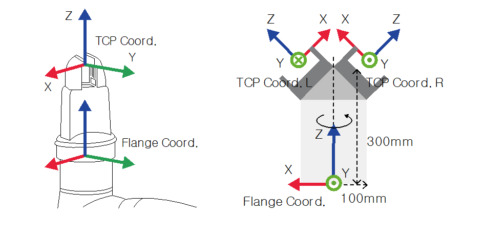
[X, Y, Z, A, B, C] = [0, 0, 100, 0, 0, 0]: General Gripper with only a Z-direction offset (TCP Coord)
[X, Y, Z, A, B, C] = [100, 0, 300, 180, -45, 0]: Left Gripper with 45-degree angle (TCP Coord. L)
[X, Y, Z, A, B, C] = [-100, 0, 300, 0, -45, 0]: Right Gripper with 45-degree angle (TCP Coord. R)
Menu
Items | Description | |
|---|---|---|
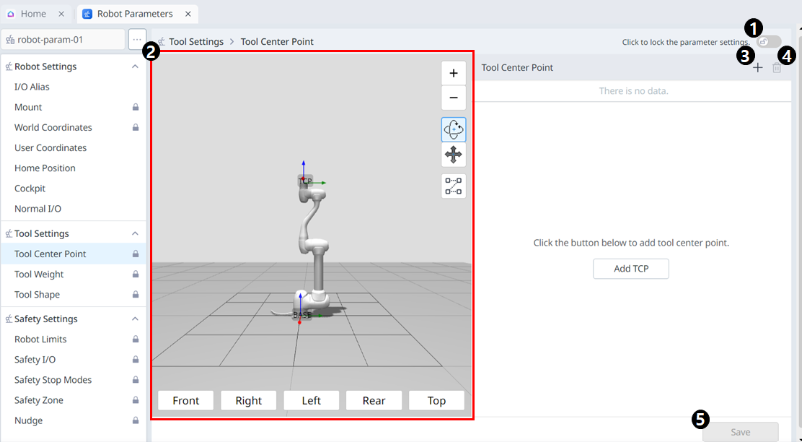
| 1 | Lock toggle button | Used to lock the set value. The safety password is required for modifying the set value. |
| 2 | 3D Simulation | This is where you can simulate the configured Tool Center Point. |
| 3 | Adding | This button allows you to add TCP. |
| 4 | Deleting | This button allows you to delete the selected TCP. |
| 5 | Save | This button allows the setting values to be saved. |
When the settings are locked, the screen below is seen.
At this time, the selected TCP is seen in blue as shown below.
Tool Weight
You can set the weight of the tool mounted on the flange by adding a Tool Weight. Tool weight can be set by selecting Robot Parameters > Tool Settings > Tool Weight.
The tool weight can be measured using the auto measure function.
It is recommended to add tool weight for each tool with a workpiece. If the workpiece weight is too heavy, the robot may recognize the weight of the workpiece as external force. It is because the robot determines this external force as a collision and stops.
When creating a task, change the weight according to the process to change the tool weight. For example, it is possible to configure a task to select the standard tool weight before picking up a workpiece, and select the tool weight with the workpiece after picking up a workpiece.
The activated tool weight Item can be set as the standard tool weight by pressing the set tool icon (![]() ) on the top of the teach pendant.
) on the top of the teach pendant.
Set of the tool setting is the same as the set of Other Commands. Set command can be used when changing the Tool Weight while a task is being performed. For more information, refer to Task Editor Module .
Note
Up to fifty different tool weights can be registered.
In the case of M series, acceleration automatically adjustment function when the maximum tool weight exceeds the maximum tool weight.
Menu
Items | Description | |
|---|---|---|
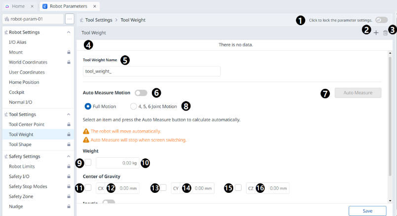
| 1 | Lock toggle button | Used to lock the set value. The safety password is required for modifying the set value. |
| 2 | Adding | This button allows you to add a new Tool Weight. |
| 3 | Deleting | This button allows you to delete a Tool Weight. |
| 4 | Tool Weight List | A list of the configured Tool Weights. |
| 5 | Tool Weight Name | This is where you can enter a name for the Tool Weight. |
| 6 | Auto Measure Motion | This button allows you to run the automatic measurement. |
| 7 | Automatic Measurement | This button allows you to select an option and run an automatic measurement for it. |
| 8 | Motion Selection | You can select the desired Motion from the options. |
| 9 | Selection of the Use of Weight | You can choose whether to use weight. This selection box is disabled for E Series or A Series without FPT sensors. |
| 10 | Weight Input | This is where you can enter the desired weight. |
| 11 | Selection of the Use of Center of Gravity CX | The use of the center of gravity CX can be selected. |
| 12 | CX Input | CX can be entered. |
| 13 | Selection of the Use of Center of Gravity CY | The use of the center of gravity CY can be selected. |
| 14 | CY Input | CY can be entered. |
| 15 | Selection of the Use of Center of Gravity CZ | The use of the center of gravity CZ can be selected. |
| 16 | CZ Input | CZ can be entered. |
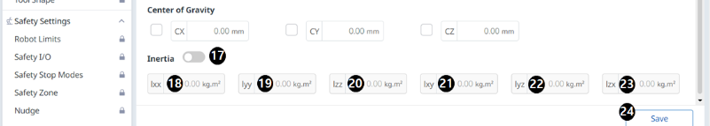
| 17 | Whether to Use Inertia | This checkbox allows you to choose whether to use inertia. |
| 18 | lxx Input | An lxx entry for inertia can be entered. |
| 19 | lyy Input | An lyy entry for inertia can be entered. |
| 20 | lzz Input | An lzz entry for inertia can be entered. |
| 21 | lxy Input | An lxy entry for inertia can be entered. |
| 22 | lyz Input | An lyz entry for inertia can be entered. |
| 23 | lzx Input | An lzx entry for inertia can be entered. |
| 24 | Save | This button allows you to save the setting values. |
Tool Shape
The shape of the tool installed on the flange can be set by adding a tool shape.
The Tool Shape can be set in Robot Parameters module > Tool Settings > Tool Shape. For more information, refer to Tool Shape.
The robot determines space limit violation status based on the TCP (Tool Center Point) of the robot end and the robot body. If the actual robot has a tool shape larger than the set TCP, a tool shape must be added to protect the workpiece and tool.
Take caution as the zone the robot can maneuver will decrease if the tool shape is set too large.
The tool shape item is only available after it is registered (Confirmed) and the toggle switch is enabled. The activated tool shape Item can be set as the standard tool shape by pressing the set tool icon (![]() ) on the top of the teach pendant.
) on the top of the teach pendant.
Set of the tool setting is the same as the set of Other Commands. Set command can be used when changing the Tool Shape while a task is being performed. For more information, refer to Task Editor Module.
Note
Up to fifty different tool shapes can be registered.
Menu
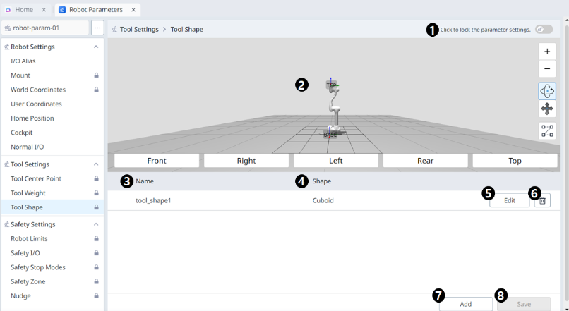
Items | Description | |
|---|---|---|
| 1 | Lock toggle button | Used to lock the set value. The safety password is required for modifying the set value. |
| 2 | 3D Simulation | This is where you can 3D Simulate the result of the configured Tool Shape. |
| 3 | Tool Shape Name | The name of the configured Tool. |
| 4 | Tool Shape Form | The shape of the configured Tool. |
| 5 | Editing Tool Shape | This button allows you to edit the configured Tool Shape. |
| 6 | Deleting Tool Shape | This button allows you to delete the selected Tool Shape. |
| 7 | Adding Tool Shape | A tool shape can be added. |
| 8 | Applying | This button allows you to apply the Tool Shape after setting it. |
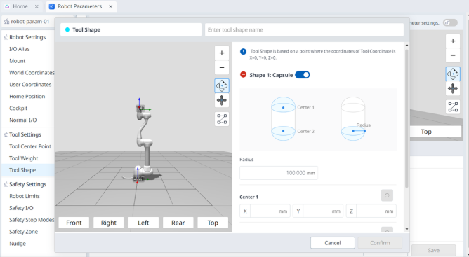
Menu
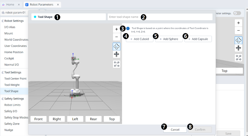
Items | Description | |
|---|---|---|
| 1 | Tool Shape | This indicates that this pane is a Tool Shape pop-up. |
| 2 | Entering a Name | This is a field where the name of the Tool Shape can be entered. |
| 3 | Cautionary Message | A note of caution when setting up |
| 4 | Add New Cuboid | This button allows you to add a cuboid. |
| 5 | Add New Sphere | This button allows you to add a sphere. |
| 6 | Add New Capsule | This button allows you to add a capsule. |
| 7 | Cancel | This button allows you to cancel the setting. |
| 8 | Confirm | This button allows you to confirm the setting. |
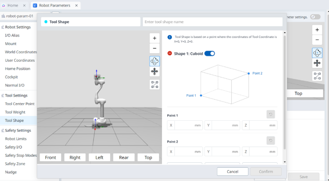
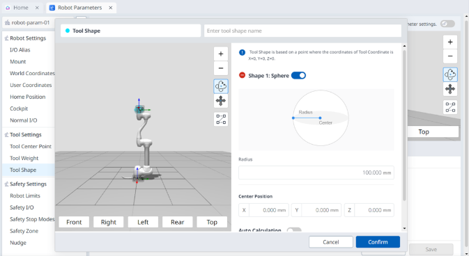
Once the cube/sphere/capsule is added, the display is seen as below.
 |  |
 |