
Menu Items
|
|
Item |
Description |
|---|---|---|
|
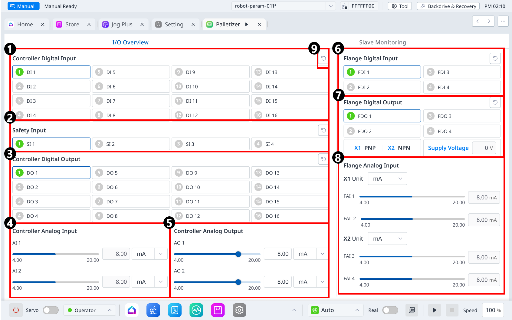
1 |
Controller Digital Input |
This section is where the controller digital input is set. |
|
2 |
Safety Input |
This section is where the safety input is set |
|
3 |
Controller Digital Output |
This section is where the controller digital output is set. |
|
4 |
Controller Analog Input |
This section is where the controller analog input is set. |
|
5 |
Controller Analog Output |
This section is where the controller analog output is set. |
|
6 |
Flange Digital Input |
This section is where the flange digital input is set. |
|
7 |
Flange Digital Output |
This section is where the flange digital output is set. |
|
8 |
Flange Analog Input |
This section is where displays the flange analog input status. |
|
9 |
Refresh |
This button allows you to change the settings to the defaults. |