The Remote Control module enables remote control to be executed for tasks that you have already created.
This module can be run at the administrator level.
Menu Layout
|
|
Item |
Description |
|---|---|---|
|
1 |
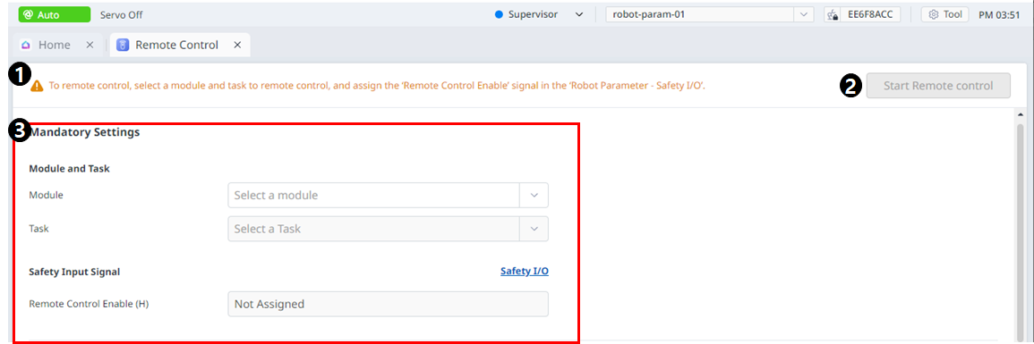
Warning |
This will show the necessary precautions when using the module. |
|
2 |
Start Remote Control |
This button allows you to start remote control after all settings have been completed. |
|
3 |
Mandatory Settings |
This is a mandatory setting for remote control. You can set modules and tasks and set safe input signals. |
|
4 |
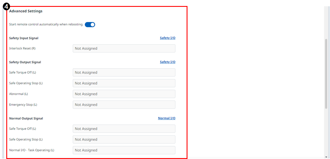
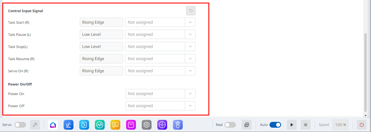
Advanced Settings |
This allows for advanced settings for remote control. You can set each port for the task to start/pause/stop/resume/servo on. If remote control is set to run automatically after rebooting, it will run as soon as Dart-Platform reboots. |
You can go to the Remote Control Mode screen when you start remote control.
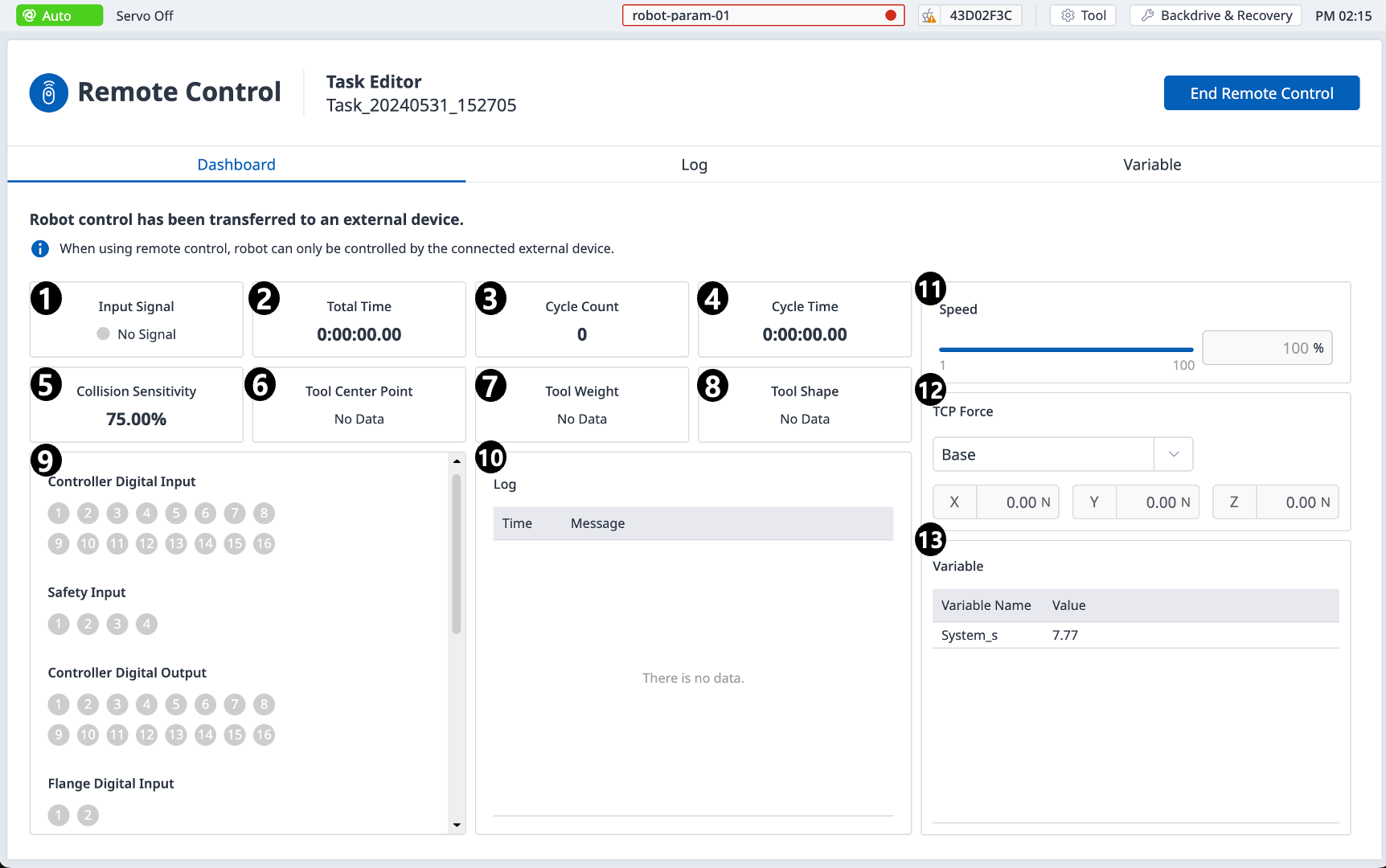
Dashboard
|
|
Item |
Description |
|---|---|---|
|
1 |
Input Signal |
Among the safety input signal items set in the safe input/output, a remote control activation signal is received and displayed. |
|
2 |
Total Time |
Displays the time when the task was executed. |
|
3 |
Cycle Count |
Displays the number of repetitions of the task. |
|
4 |
Cycle Time |
Displays the one-cycle time of the task. |
|
5 |
Collision Sensitivity |
Displays the collision sensitivity value. If inside the zone, displays the impact sensitivity value set in that zone. If outside the Zone, displays the crash sensitivity value set in the robot limit. |
|
6 |
Tool Center Point |
Displays the tool center point specified in the task. |
|
7 |
Tool Weight |
Displays the tool weight specified in the task. |
|
8 |
Tool Shape |
Displays the tool shape specified in the task. |
|
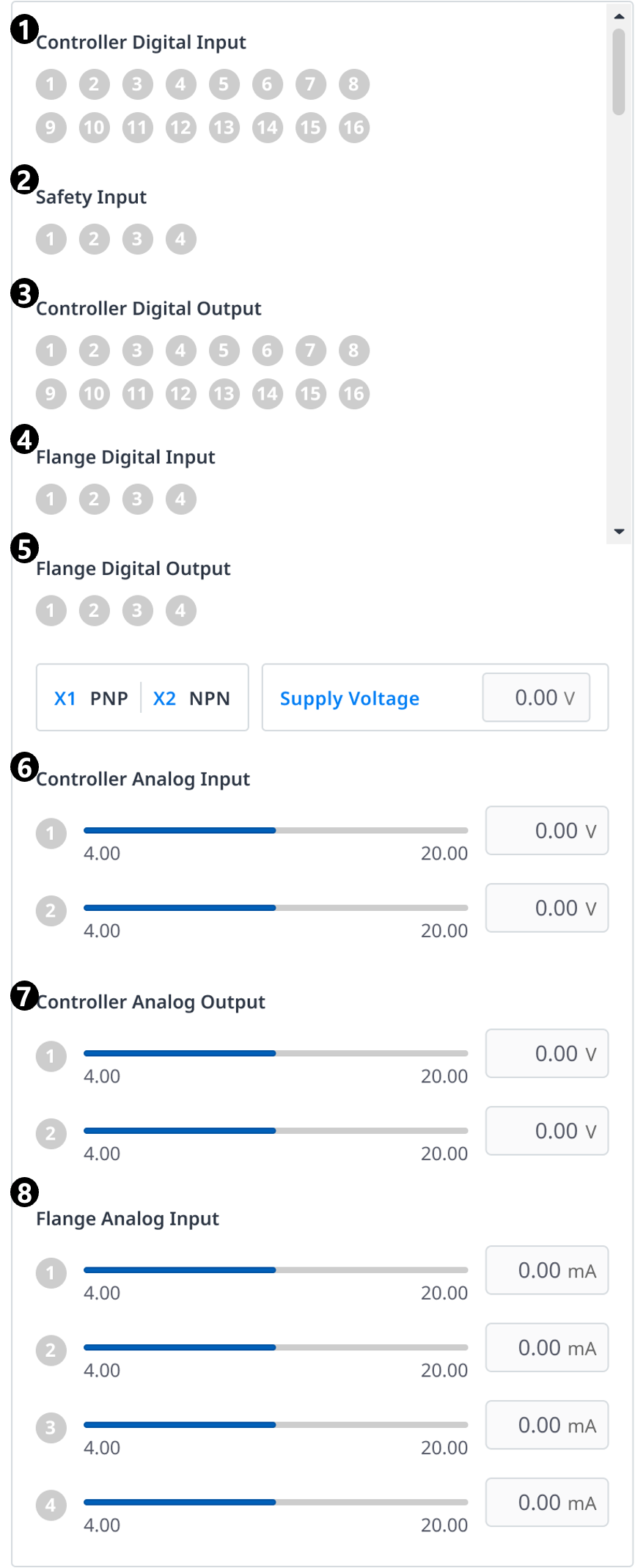
9 |
Signal Input/Output |
Displays the respective signal input/output values. |
|
10 |
Log |
Displays system log information. |
|
11 |
Speed |
You can set the speed of the task. |
|
12 |
TCP Force |
Displays the force applied to TCP in real time. |
|
13 |
Variable |
Displays the variable values used by the running task. |
|
|
Item |
Description |
|---|---|---|
|
1 |
Controller Digital Input |
Displays the controller digital input settings. |
|
2 |
Safety Input |
Displays the controller safety input settings. |
|
3 |
Controller Digital Output |
Displays the controller controller digital output settings. |
|
4 |
Flange Digital Input |
Displays the flange digital input settings. |
|
5 |
Flange Digital Output |
Displays the flange digital output settings. |
|
6 |
Controller Analog Input |
Displays the controller analog input settings. |
|
7 |
Controller Analog Output |
Displays the controller analog output settings. |
|
8 |
Flange Analog Input |
Displays the flange analog input settings. |
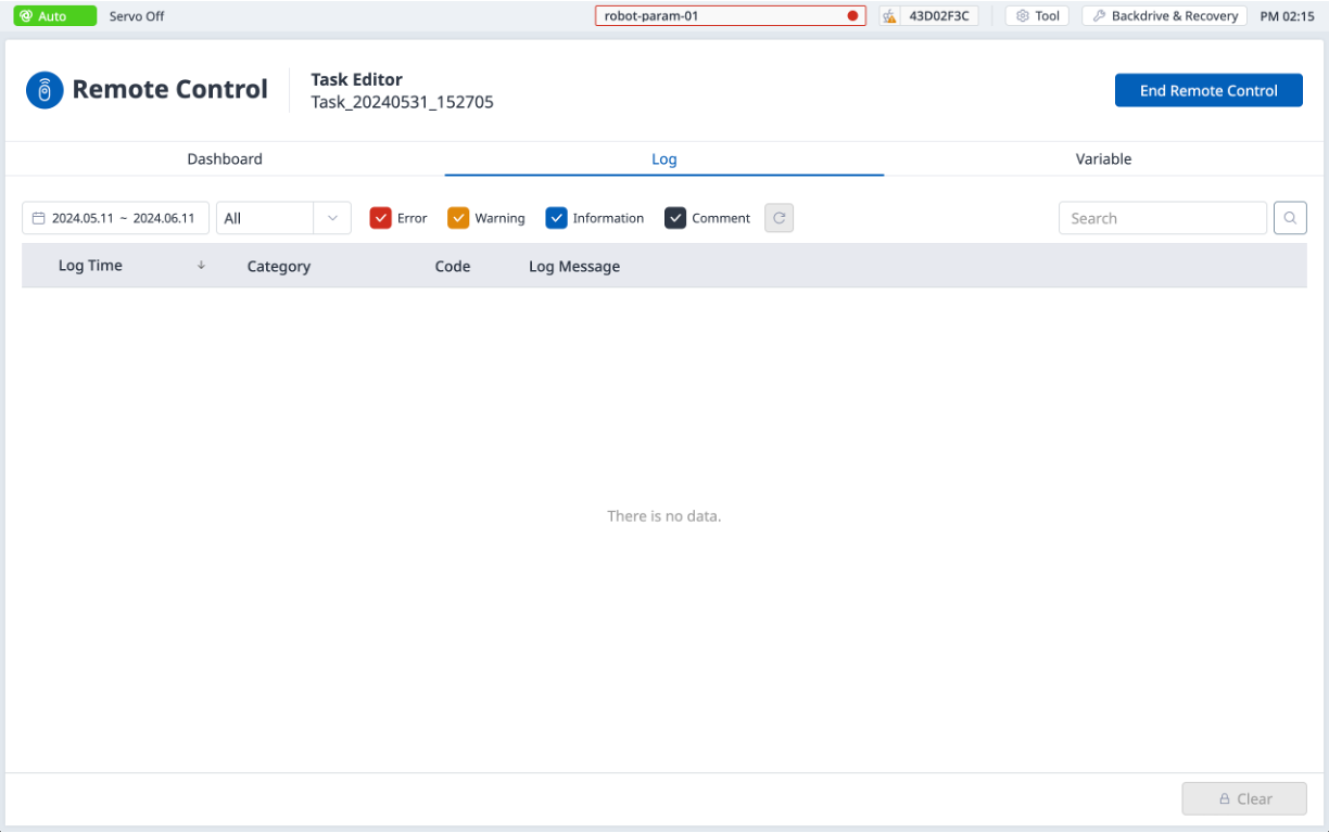
Log
Displays system log information.
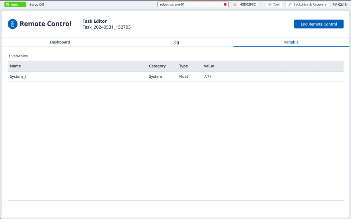
Variable
Displays the variable values used by the running task.