
Robot Welding
In the previous section, it was mentioned that skilled welding personnel will adjust (1) the welding conditions (voltage/wire supply speed/current) and (2) the movements of the torch. Robot welding replaces the work performed by welding personnel with work automated by robots. Robot welding allows for welding conditions which were previously controlled by welding personnel using separate controlling devices. (1) The robot’s teaching pendant screen can be used for adjustments, and (2) the torch that was once moved by hand is attached to the tip of the robot arm, to be controlled via specialized motions and the teaching feature through the saving of the work path.
With robot welding, the syncing between the robot, which moves the torch, and the welder, which creates the arcs from the torch, is very important. Mutual syncing signals must be exchanged. In particular, information regarding abnormal conditions that can occur during welding (low protective gas, no more wire, robot collision, malfunctions in the welder, etc.) must be mutually checked between the robot controller and welder to prevent danger. The following is a list of the functions required by robot systems for robot welding.
Connecting and setting of the welder interface
- Connection method: Analog-I/O, Digital-I/O channels or by connecting an external interface device of the same type
- Communication method: EtherNet/CAN communication/serial communication or by connecting an external interface device of the same type
- Interface setting and syncing signal setting
Welding process syncing function
Each welding method has a small process which lasts from the moment the user presses the switch on the torch to start welding to the moment protective gas is no longer being emitted and welding comes to a stop. This is called a welding process.
An example of a welding process performed by hand would be: (1) Torch switch is turned on (welding process begins) → (2) protective gas is turned on (for a set period) → voltage release/slow feeding (for a set period) → arc occurrence → starting voltage/feeding speed conditions are maintained (for a set period) → main voltage/feeding speeds are maintained & (3) the torch is moved by the welding personnel → (4) the torch is switched off but is held in place → (5) adjustment to the ending voltage/feeding speed (for a set period) → voltage/feeding ended & protective gas maintained (for a set period) → protective gas shut off (welding process ended) → (6) torch is no longer held in position. As you can see, when the switch is turned on and off by the user, those are endpoints of a series of welder actions to control gas, voltage, and wire supply quantity in order to perform welding. In order to perform welding process syncing through the use of robots, steps (1), (3), (4), and (6), which are performed by hand, can be replaced with automated robot processes as seen below. (1) Welding work signal-high is sent (3) Welding motion begins after current flow signal is acquired (4) Welding work signal-low is sent after welding motion comes to an end (6) Syncing ends after welding process end signal is acquired
In the above example of robot welding, the detailed process settings must be set by experts in the relevant processes. In addition, in cases where abnormalities are found during the welding process and welding comes to an unforeseen stop, the welding process must be followed until shutdown in order to minimize defects in the resulting product.
Welding condition setting/ auxiliary device adjustment
In addition to a separate user interface (UI) device for inputting settings, welders offer a number of adjustable variables in order to output the desired welding quality in a variety of welding environments. In robot welding, the welder’s UI can be used to control the adjustable welding conditions, which are unified in the robot controller UI. Auxiliary devices of the welder, such as the wire feeder, gas valve, etc., can be directly controlled, allowing for replacement of consumables and preventive maintenance through the robot controller UI. However, welders can differ depending on the brand, and support is usually limited to certain brands.
Welding status monitoring
This allows workers to check information related to welding quality while welding is in progress. Welding status information includes welding current, voltage, wire feeding speed, normal gas discharge status, etc., and any abnormalities or detailed error codes produced by the welder are also shown.
If the above functions can be said to be for the sake of syncing with the welder, the below are robot motion functions necessary for welding work.
Pose-maintaining motion
It is necessary to keep the torch's angle consistent with the welding path in order to produce uniform welding results. While the user is teaching path points, the angle can be maintained; however, when teaching complex forms or circular arc path points, it will be difficult to maintain the angle of the torch in a consistent fashion with respect to the path. Using the angle maintaining feature will allow welding with relatively consistent welding (torch) angles with respect to the path.
Weaving motion
A motion that repeatedly shakes the torch laterally with regard to the direction of the welding path is called a weaving motion. Using a weaving motion will fuse the area around the welding line more broadly to create broad welding beads; this is often used for cases where gaps have occurred in the welding area. Robots offer various types of weaving trajectories and options for controlling them.
Path offset/multi-pass welding
If the material is thick, a single welding pass may not be sufficient. In such a scenario, an offset is created from the central path and multiple passes are performed to satisfy the welding strength of the material. For this purpose, there is a feature for changing offsets for the teaching path and its motion. There is a separate function for multi-pass welding as well.
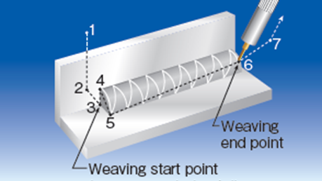
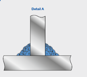
| Example of a weaving motion | Cross section of multi-pass welding using an offset |
Seam tracking
If the target material is placed differently from the original teaching position, a feature to automatically adjust the teaching point is necessary. If distortions in the material create errors in the welding path, a feature must exist to correct the path during the welding process to match the target. Touch sensors which detect the location of the material using welding wires are mainly used for teaching point correction; laser vision sensors using line lasers or arc sensors that detect the current created by the welding are used to acquire path errors for path correction. A specialized function to reflect the acquired error in the welding path and correct it is also sometimes supported.