
Tool Center Point (TCP) Setting
When configuring the tool center point (TCP), the position and rotation angle based on the flange coordinates must also be defined. The distance from the default starting point of the flange coordinate to the tool center point (TCP)in the X, Y and Z directions cannot be set to be greater than 10000 mm. In addition, if the converted lengths (
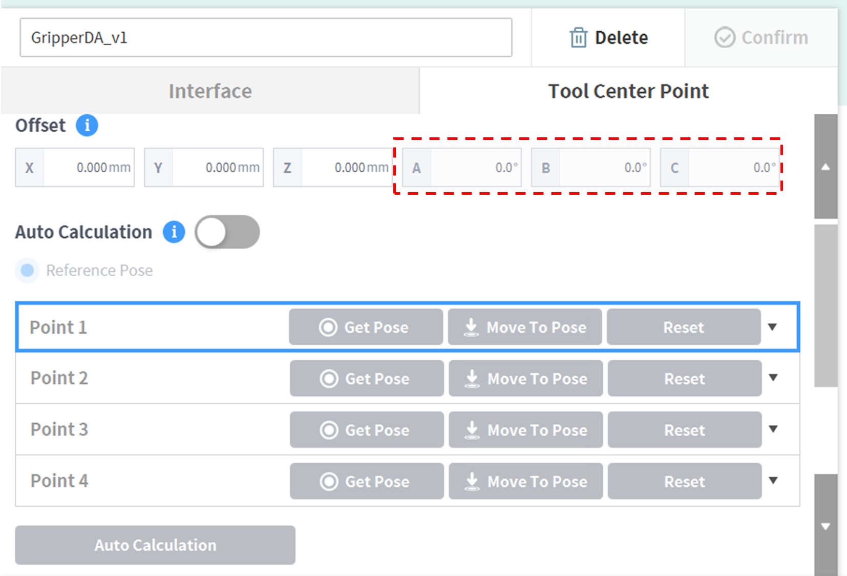
In particular, if the TCP is configured using Auto Calculate, the calculation is made based only on the X, Y and Z positions, so it is necessary to enter the rotation angle. The rotation angle can be defined with items A, B and C, and it is based on the Euler Z-Y-Z rotation method.
The definitions of the coordinate axis expressed with x, y, z and coordinate axis expressed with X, Y, Z are as follows:
- Coordinate axis of “Flange Coordinate” (x, y, z): The coordinate axis direction defined at the end of the flange is identical to the robot coordinate with a robot joint angle of (0,0,0,0,0,0).
- Coordinate axis of “TCP Coordinate” (X,Y,Z): The coordinate axis is defined at the end of the tool installed on the end of the flange or working point. The rotation angle of the “TCP Coordinate” is defined based on the “Flange Coordinate” in the order of 1) to 3) of the following:
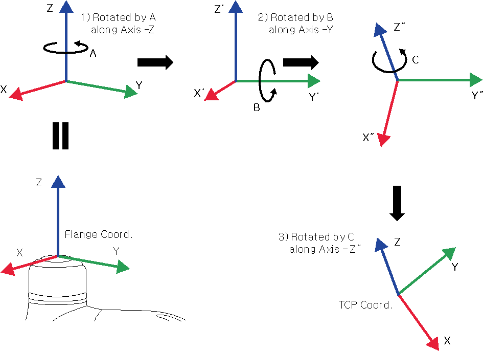
1) Rotate A degrees along the z axis of the Flange Coordinate
2) Rotate B degrees along the y’ axis of the coordinate rotated according to 1)
3) Rotate C degrees along the z’’ axis of the coordinate rotated according to 2)
Here are a few examples of configuring the TCP according to the method described above:
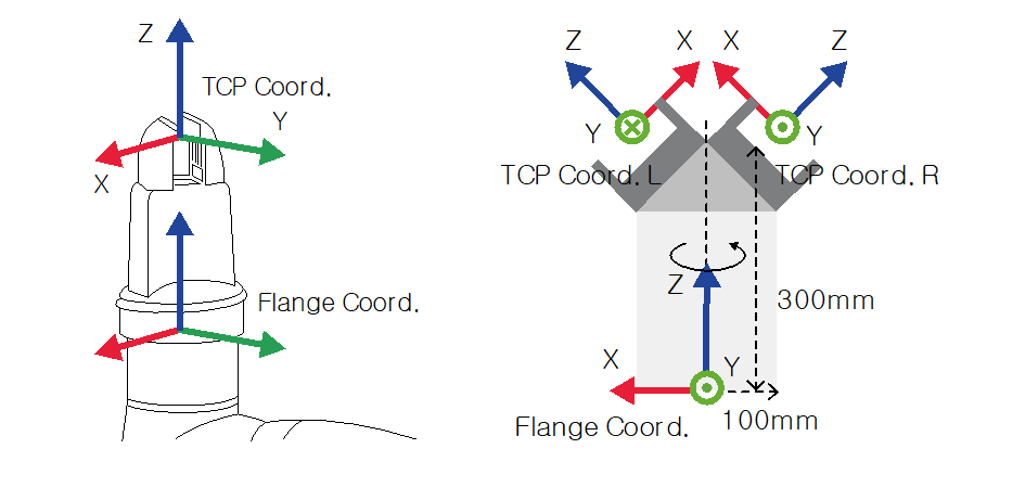
- [X, Y, Z, A, B, C] = [0, 0, 100, 0, 0, 0]: General Gripper with Z-direction offset (TCP Coord)
- [X, Y, Z, A, B, C] = [100, 0, 300, 180, -45, 0]: Left Gripper with 45-degree angle (TCP Coord. L)
- [X, Y, Z, A, B, C] = [-100, 0, 300, 0, -45, 0]: Right Gripper with 45-degree angle (TCP Coord. R)