
Installation (CS-04)
Cautions During Installation
Caution
- Secure sufficient space for installation before installing the controller If not enough space is secured, the controller may be damaged or the manipulator or Teach Pendant cable may become broken.
- Check the input power supply when connecting power to the product. If the connected input power supply is different from the rated power input (22-60 VDC), the product may not operate properly or the controller may be damaged.
Installation Environment
When installing the controller, consider the following.
- Secure sufficient space for installation before installing the controller.
- The controller must be fixed.
- Make sure all components are fixed during installation in portable mobile equipment.
Hardware Installation
Install the manipulator, controller and pendants (emergency stop button), which are the necessary elements of system, before operating of the robot, and then connect the power. The installation method of each component is as follows:
Connecting the Manipulator and the Controller
Push the manipulator connection cable into the corresponding controller connector until a click is heard. This will prevent the cable from becoming loose.
Caution
- Do not disconnect the manipulator cable while the robot is turned on. This can cause damage to the robot.
- Do not modify or extend the manipulator cable.
- When installing the controller on the floor, secure at least 50 mm of space on each side of the controller to enable ventilation.
- Make sure that the connectors are properly connected before turning on the controller.
Note
- When configuring the system, it is recommended that a noise reducer be installed to prevent noise influence among the devices and system malfunction.
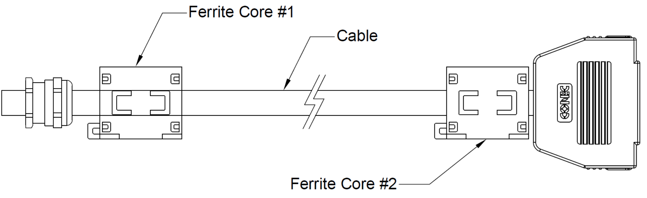
- If the controller is affected by the noise generated by electromagnetic waves, it is recommended that ferrite cores be installed on each end of the manipulator cable to ensure normal operation. The installation locations are as follows:
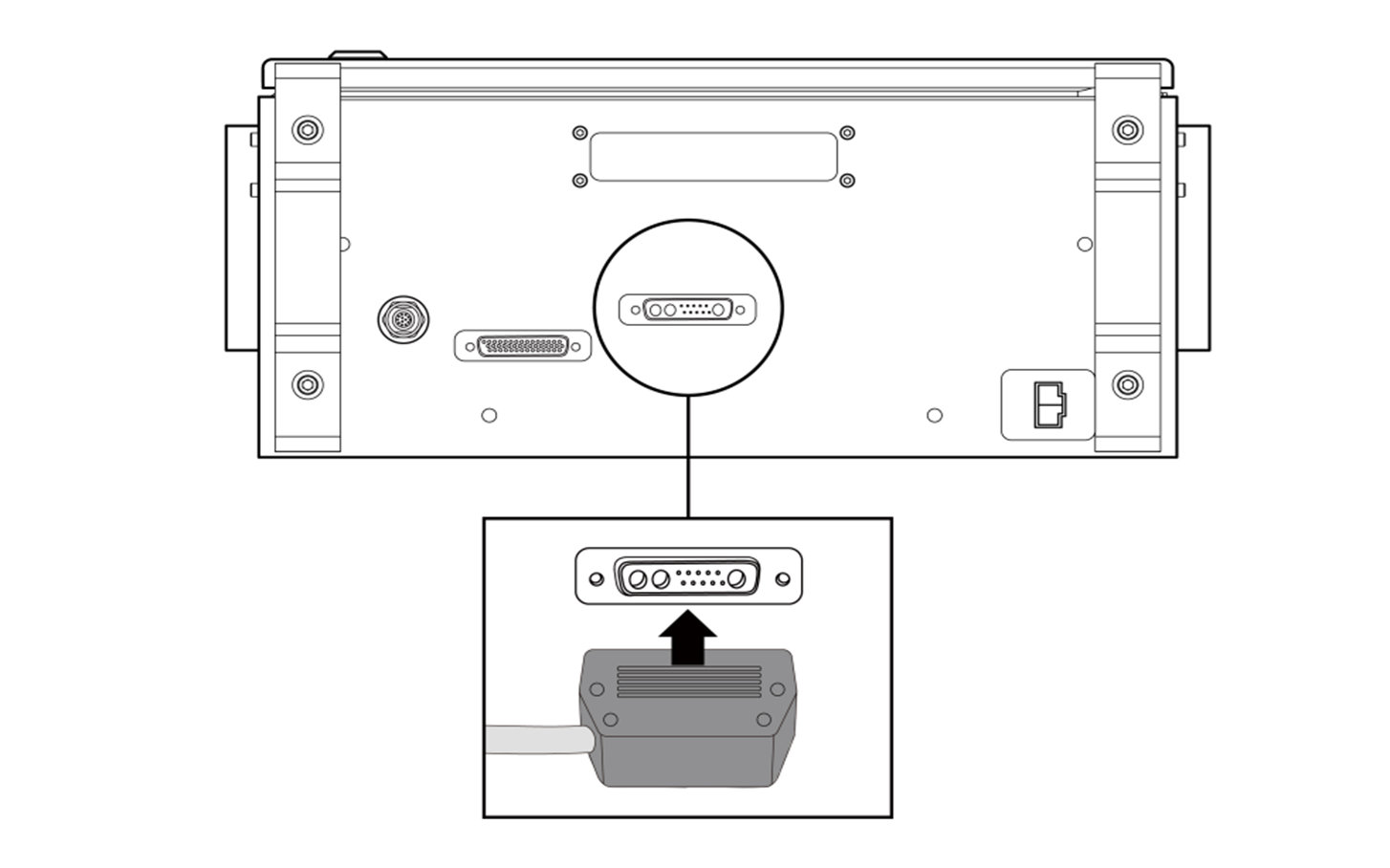
Connecting the Controller and the Emergency Stop Button
Connect the emergency stop button cable to the corresponding controller connector and engage the screw lock by turning it clockwise to prevent the cable from becoming loose.
Warning
- Set the emergency stop button setting switch according to “Emergency Stop Button Setting Switch”.
- If the switch setting is different from the actual configuration, the emergency stop button may not operate properly in an emergency, which could result in injuries. Make sure to check the settings and operation of the emergency stop button.
Caution
- Make sure to check the connector shape before connecting the cable.
- If the emergency stop button is used, be careful not to trip on the connecting cables.
- Be careful not to , allow the controller, emergency stop button or cables to come in contact with water.
- Do not install the controller or emergency stop button in a dusty or wet environment.
- The controller and emergency stop button must not be exposed to dust conditions exceeding IP40 ratings. Be especially careful in environments with conductive dust.
- Do not disconnect the emergency stop button cable during robot operation.
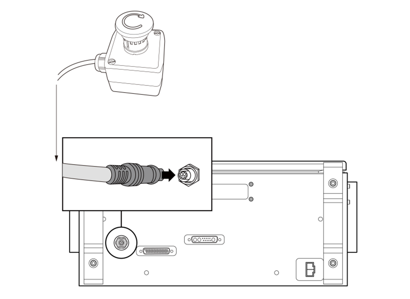
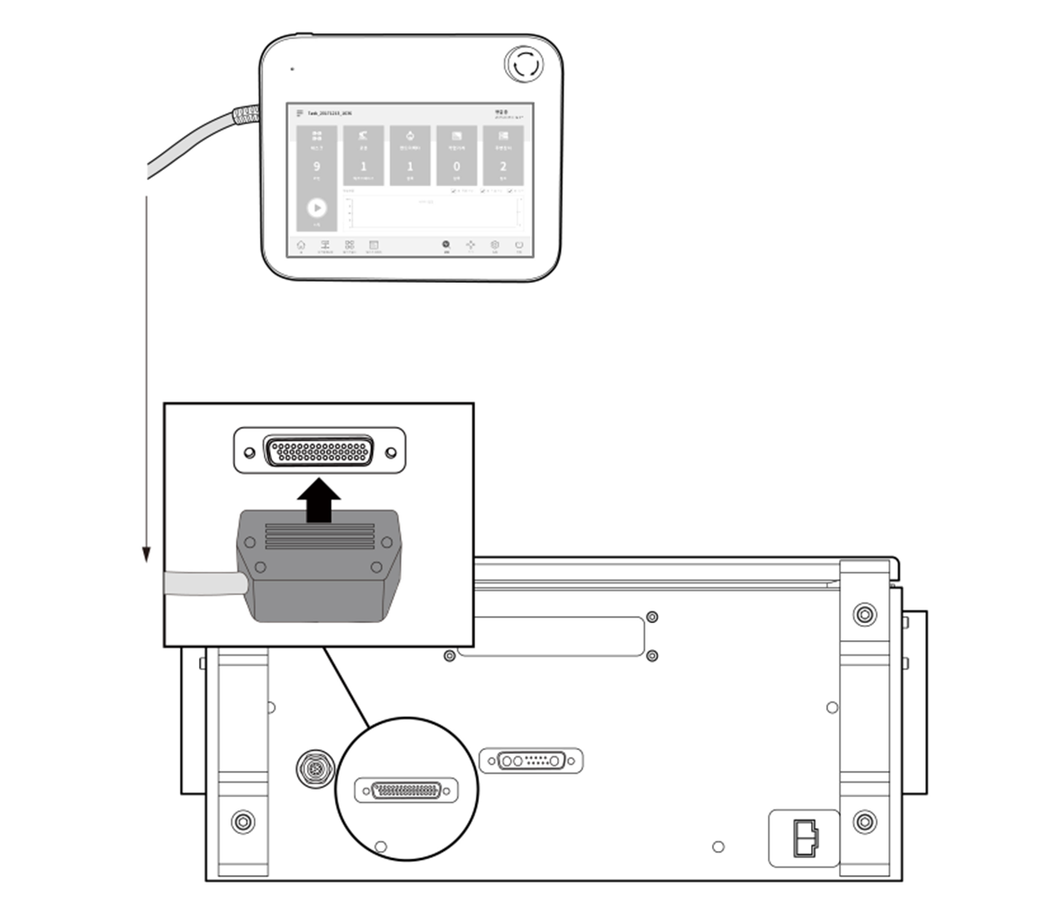
Connecting the Controller and the Smart Pendant
Connect the Smart Pendant cable to the corresponding controller connector and engage the screw lock by turning it clockwise to prevent the cable from becoming loose.
Warning
- Set the emergency stop button setting switch according to “Emergency Stop Button Setting Switch”. If the setting switch of the emergency stop button is different from the actual configuration, the emergency stop button may not operate properly in an emergency, which could result in injuries. Make sure to check the settings and operation of the emergency stop button.
Caution
- Make sure to check that the pins in the cable end are not damaged or bent before connecting the cable.
- If the Smart Pendant is used by hanging it on the wall or on the controller, be careful not to trip on the connecting cables.
- Be careful not to allow the controller, Smart Pendant or cables to come in contact with water.
- Do not install the controller or Smart Pendant in a dusty or wet environment.
- The controller and Smart Pendant must not be exposed to dust conditions exceeding IP20 ratings. Be especially careful in environments with conductive dust.
- Ensure that the curvature of the Smart Pendant cable is greater than the minimum curvature radius (120 mm).
Note
- When configuring the system, it is recommended that a noise reducer be installed to prevent noise influence among devices and system malfunction.
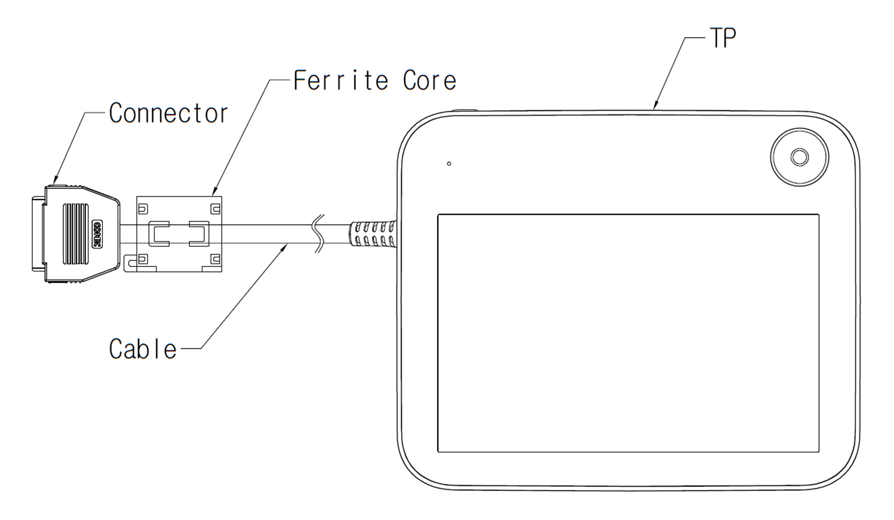
- If the Smart Pendant is affected by the noise generated by electromagnetic waves, it is necessary to install a ferrite core to ensure normal operation. The installation locations are as follows:
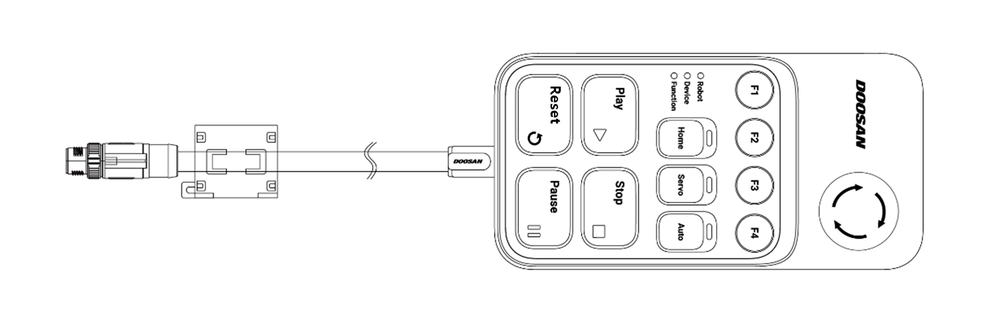
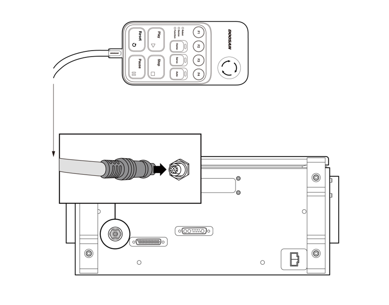
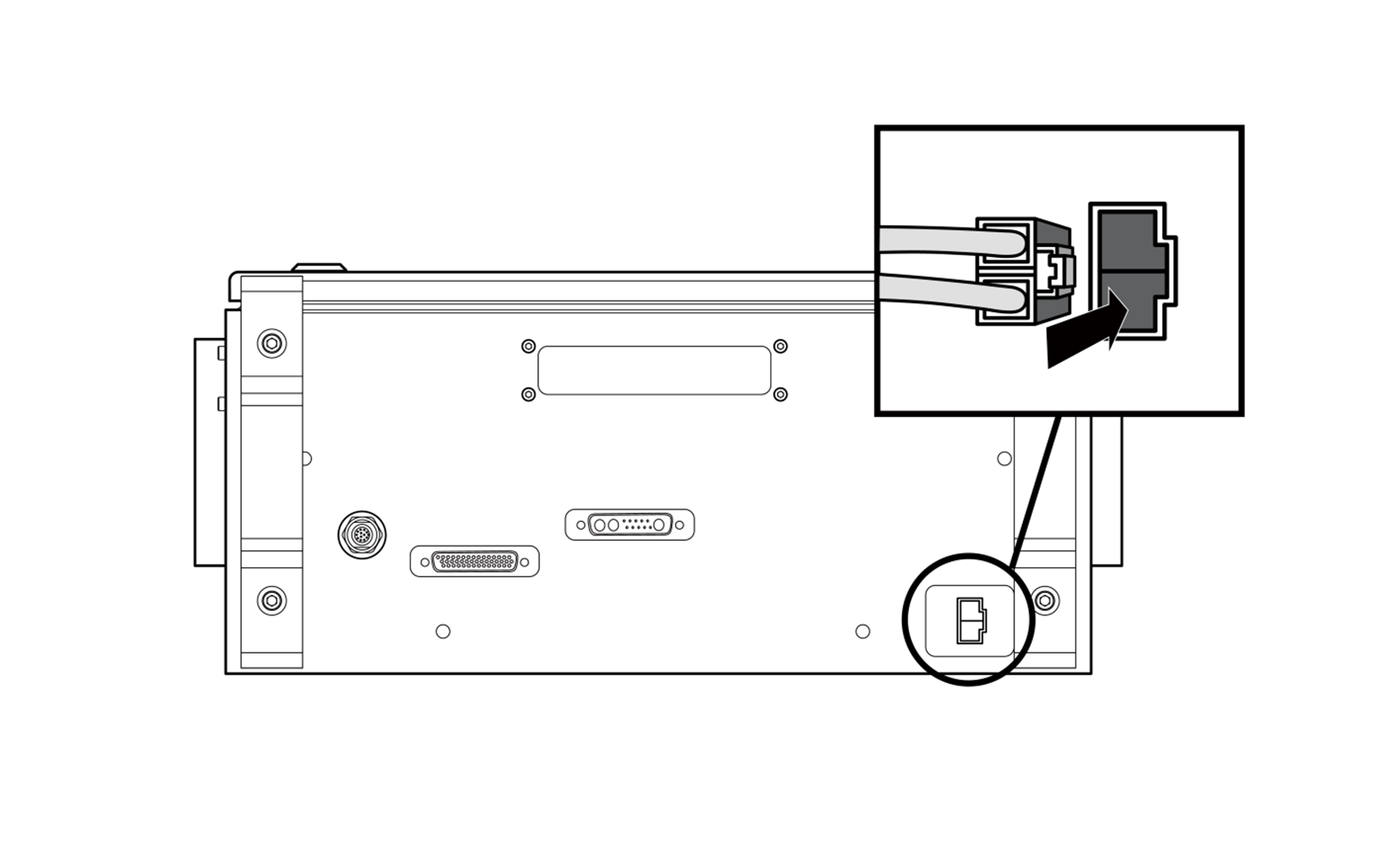
Connecting the Controller and the Teach Pendant
Push the Teach Pendant cable into the corresponding controller connector until a click is heard. This will prevent the cable from becoming loose.
Warning
- Set the setting switch of the emergency stop button (A-Series) according to “Emergency Stop Button Setting Switch”. If the setting switch of the emergency stop button is different from the actual configuration, the emergency stop button may not operate properly in an emergency, which could result in injuries. Make sure to check the settings and operation of the emergency stop button.
Caution
- Make sure to check that the pins in the cable end are not damaged or bent before connecting the cable.
- If the Teach Pendant is used by hanging it on the wall or on the controller, be careful not to trip on the connecting cables.
- Be careful not to allow the controller, Teach Pendant or cable to come in contact with water.
- Do not install the controller or Teach Pendant in a dusty or wet environment.
- The control box and Teach Pendant must not be exposed to a dusty environment that exceeds IP20 ratings. Be especially careful in environments with conductive dust.
Note
- When configuring the system, it is recommended that a noise reducer be installed to prevent noise influence among devices and system malfunction.
- If it is affected by noise generated by electromagnetic waves, it is recommended that ferrite cores be installed on the connection parts of the Teach Pendant cable to ensure normal operation. The installation locations are as follows:
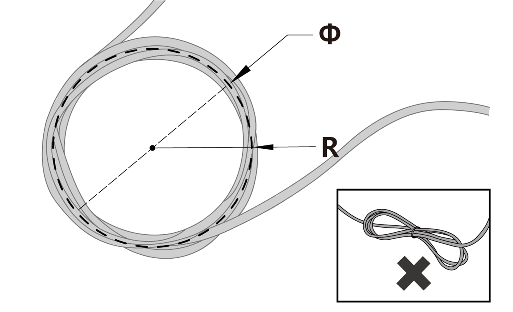
Arranging the Cables
Ensure that the cables have curvatures greater than the minimum curvature radius. The minimum curvature radius of each cable is as follows:
Cable | Minimum Curvature Radius (R) |
Teach Pendant cable | 120 mm |
Manipulator cables | 120 mm |
Smart Pendant cable | 100 mm |
Emergency stop button cable | 100 mm |
Caution
- Ensure that the each connection part of the Teach Pendant is greater than the minimum curvature radius (120 mm).
- If the curvature radius is smaller than the minimum curvature radius (120 mm), cable disconnection or product damage may occur.
- In environments exposed to noise generated by electromagnetic waves, install suitable cables and take other measures to prevent malfunction.
Connecting Controller Power
Push the power cable into the corresponding controller connector until a click is heard. This will prevent the cable from becoming loose.
Warning
- After connecting the power cable, make sure that the robot is properly grounded (electrical ground connection). Establish a common ground for all equipment in the system with unused bolts related to the ground symbol inside the controller. The ground conductor must satisfy the maximum current rating of the system.
- Protect the input power of the controller using devices such as a circuit breaker.
- Do not modify or extend the manipulator cable. This can cause a fire or controller breakdown.
- Make sure that all cables are properly connected before supplying power to the controller. Always use the original cable included in the product package.
- Be careful not to connect the polarity of the input voltage incorrectly.
Note
- Whenconfiguring the system, it is recommended that a power switch be installed that can turn off power to all devices in the system at once.
- If a controller for the DC is used, the robot’s movement may be limited according to the load and motion.
- If the input voltage is 48 V or less, the robot’s movement may be limited according to the load and motion.
- The power supply must satisfy minimum requirements such as grounding and circuit breakers. The electrical specifications are as follows:
Parameter | Specifications |
Input Voltage | 22 – 60 VDC |
Rated Input Current | 30 A |