How to set the shape of the Space Limit/Zone is as follows.
Items
Description
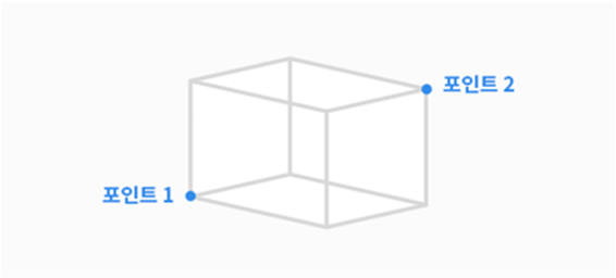
Cuboid
The shape of the Space Limit/Zone is created as a cuboid.
Enter the lower endpoint (Point 1) and upper endpoint (Point 2) of the cuboid and tap the Save Pose button.
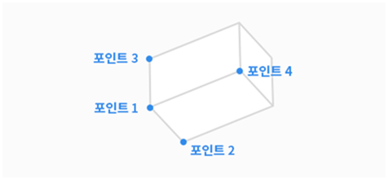
Tilted Cuboid
The shape of the Space Limit /Zone is created as a tilted cuboid.
Setting by 4 Points
Enter the reference point (point 1), x-axis end point (point 2), y-axis end point (point 3), and z-axis end point (point 4)of the tilted cuboid and tap the Save Pose button.
3 lines (Point 1-Point2, Point 1-Point 3, Point 1-Point 4) must cross each other at a right angle. (a deviation of +/- 5 degrees is acceptable)
If you use constrained motion functions such as "Plane Constraint" and "Axis Constraint" in the Cockpit using Point 1 as the reference point, the points for point 2, point 3, and point 4are more easily found.
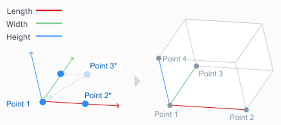
Setting by 3 Points and Height
Enter the reference point (Point 1), the point on the x-axis (Point 2), and the point on the xy-plane (Point 3).
The location of the point on the xy-plane(Point 3) determines the direction of the y-axis, which is perpendicular to the line formed by the reference point (point 1) and the point on the x-axis (point 2) and located on the xy-plane.
Once the reference point, x-axis direction, and y-axis direction are determined, the z-axis direction is determined by the right-hand rule.
After the reference point and three axis directions are determined, the size of the tilted cuboid can be specified by setting the length, width, and height.
Tilted cuboid can be moved parallel (parallel translation) by setting the x, y, and z offset.
After reaching the endpoint(vertex) of the tilted cuboid by pressing “move to” beside Actual Point 1, then pressing the “move to” beside Actual Point 2, Actual Point 3, or Actual Point 4, Robot TCP will move it along the edge of the tilted cuboid as far as it can reach. The position and direction setting of the tilted cuboid can be verified this way.
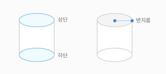
Cylinder
The shape of the Space Limit/Zone is created as a cylinder.
Enter the point at a radius distance, the point of the upper plane and the point of the lower plane of the cylinder, and tap the Save Pose button.
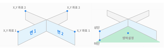
Multi-plane Box
The shape of the Space Limit/Zone is created as a multiplane box.
Set the height of the top and bottom of the multi-plane box and press the Add Pose button to add a plane.
Select X and Y coordinates to set the direction of the plane and tap the Save Pose button. Up to 6 planes can be configured.
Set the coordinates of the point on the area you want to set.
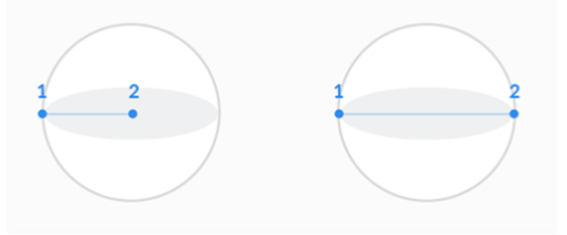
Sphere
The shape of the Space Limit/Zone is created as a sphere.
To configure the radius, enter the positions of the center point and endpoint of the sphere, and to configure the diameter, enter two endpoints of the sphere, then tap the Save Pose button.
JavaScript errors detected
Please note, these errors can depend on your browser setup.
If this problem persists, please contact our support.