
Safety Zone
Safety Zone settings screen
Menu
Items | Description | |
|---|---|---|
| 1 | Lock toggle button | Used to lock the set value. The safety password is required for modifying the set value. |
| 2 | Choose Whether to Enable | This button allows you to apply/unapply the created Safety Zone. |
| 3 | Zone Name | The name given by the user when creating the Safety Zone |
| 4 | Zone Type | Safety Zone types (each type has different parameters to set)
|
| 5 | Zone shape | Safety Zone shapes
|
| 6 | Edit |
|
| 7 | Delete | This button allows the safe zone to be deleted. |
| 8 | Add |
|
| 9 | Save | This button allows any changes to the settings in relation to the Safety Zone to be saved. |
Sphere
Menu
Items | Description | |
|---|---|---|
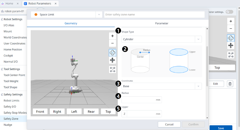
| 1 | Shape Type | The desired Shape type can be selected from this drop-down. |
| 2 | Shape Image | This is the area where the image of the selected type is seen. |
| 3 | Coordinates | Either Base or World coordinates can be selected from this drop-down. |
| 4 | Radius | This is where the radius value is entered. |
| 5 | Center Position | The center value can be set in these fields for each of the X-, Y-, and Z-axes. |
| 6 | Auto Calculation | This button allows the Auto Measure option to be enabled. |
| 7 | Auto Calculation Image | This area is where the image required for Auto Measure is seen. This appears when the Auto Measure option is enabled. |
| 8 | Point 1 | Each field is where the value for Point 1 is entered. |
| 9 | Point 2 | Each field is where the value for Point 2 is entered. |
| 10 | Auto Calculate | This button allows the Auto Calculate to be executed. |
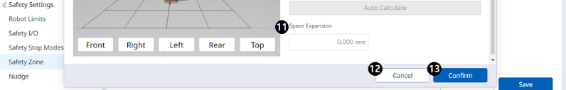
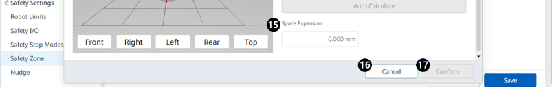
| 11 | Space Expansion | This field is where the Space Expansion can be set. |
| 12 | Cancel | This button allows the setting to be canceled. |
| 13 | Confirm | This button allows you to confirm the setting. |
Cylinder
Menu
Items | Description | |
|---|---|---|
| 1 | Shape Type | The desired Shape type can be selected from this drop-down. |
| 2 | Shape Image | This is the area where the image of the selected type is seen. |
| 3 | Coordinates | Either Base or World coordinates can be selected from this drop-down. |
| 4 | Radius | This is where the radius value is entered. |
| 5 | Upper | This field is where the upper value is entered. |
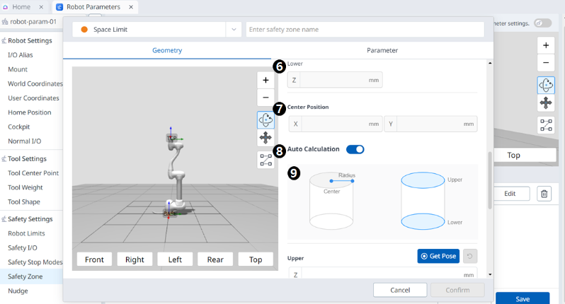
| 6 | Lower | This field is where the lower value is entered. |
| 7 | Center Position | The center value can be set in these fields for each of the X- and Y-axes. |
| 8 | Auto Calculate | This button allows the Auto Measure option to be enabled. |
| 9 | Auto Calculate Image | This area is where the image required for Auto Measure is seen. This appears when the Auto Measure option is enabled. |
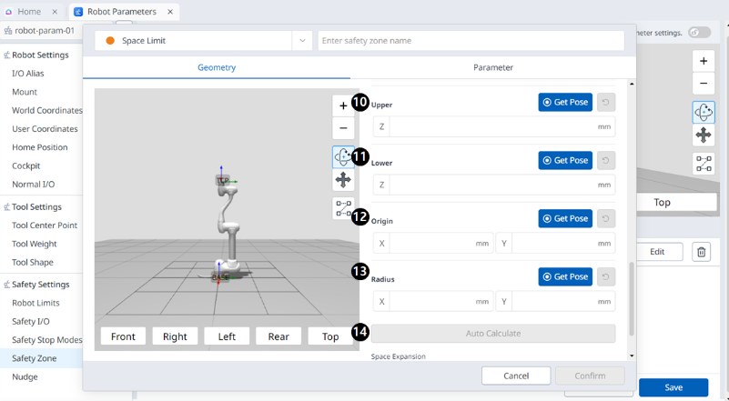
| 10 | Upper | This field is where the upper value is entered. |
| 11 | Lower | This field is where the lower value is entered. |
| 12 | Origin | This field is where the origin value is entered. |
| 13 | Radius | This field is where the radius value is entered. |
| 14 | Auto Calculate | This button allows the Auto Calculate to be executed. |
| 15 | Space Expansion | This field is where the Space Expansion can be set. |
| 16 | Cancel | This button allows the setting to be canceled. |
| 17 | Confirm | This button allows you to confirm the setting. |
Cuboid
Menu
Items | Description | |
|---|---|---|
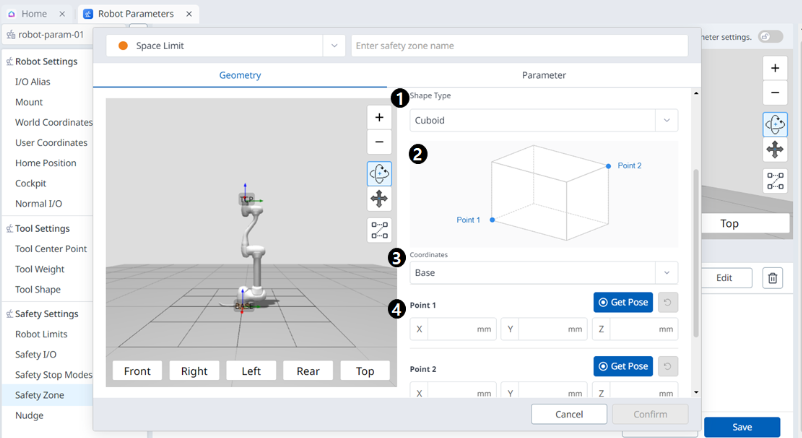
| 1 | Shape Type | The desired Shape type can be selected from this drop-down. |
| 2 | Shape Image | This is the area where the image of the selected type is seen. |
| 3 | Coordinates | Either Base or World coordinates can be selected from this drop-down. |
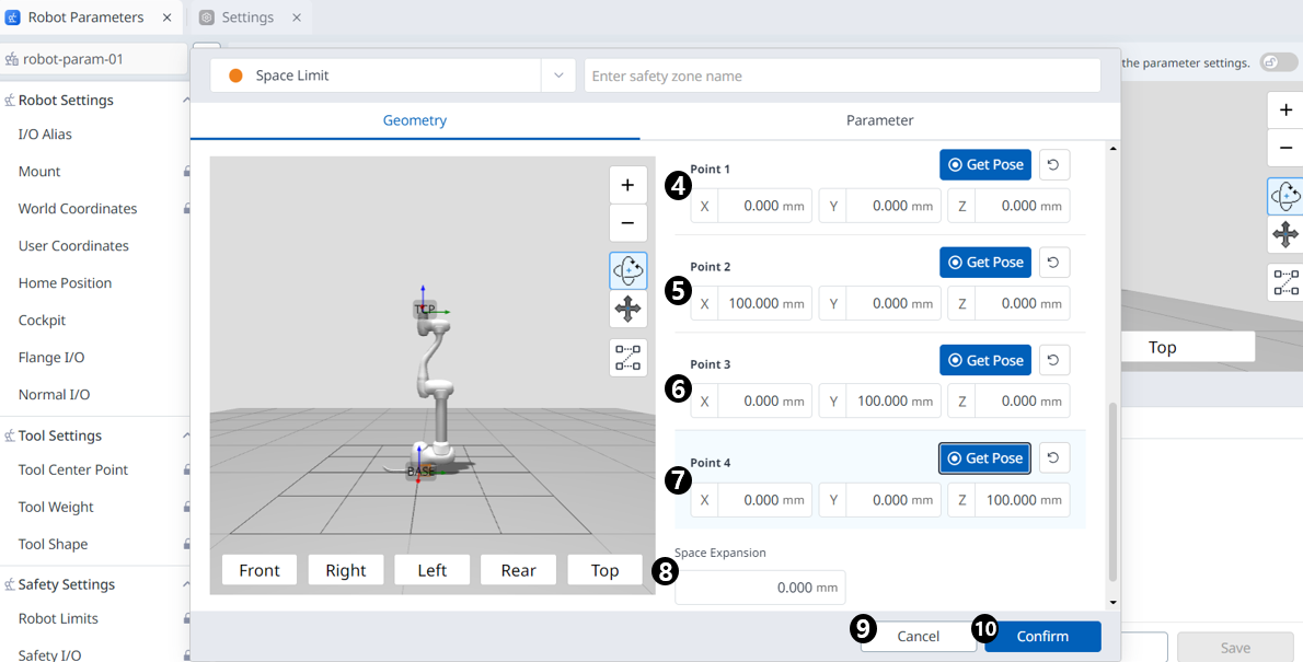
| 4 | Point 1 | Each field is where the value for Point 1 is entered. |
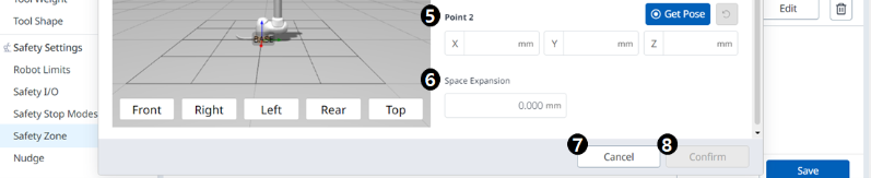
| 5 | Point 2 | Each field is where the value for Point 2 is entered. |
| 6 | Space Expansion | This field is where the Space Expansion can be set. |
| 7 | Cancel | This button allows the setting to be canceled. |
| 8 | Confirm | This button allows you to confirm the setting. |
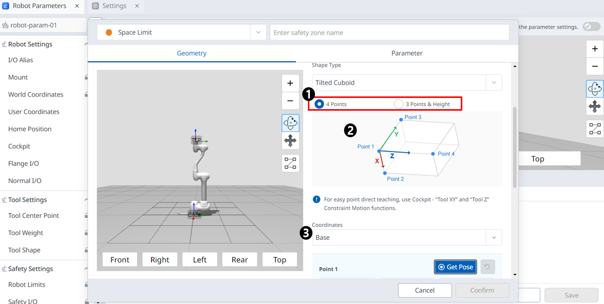
Tilted Cuboid
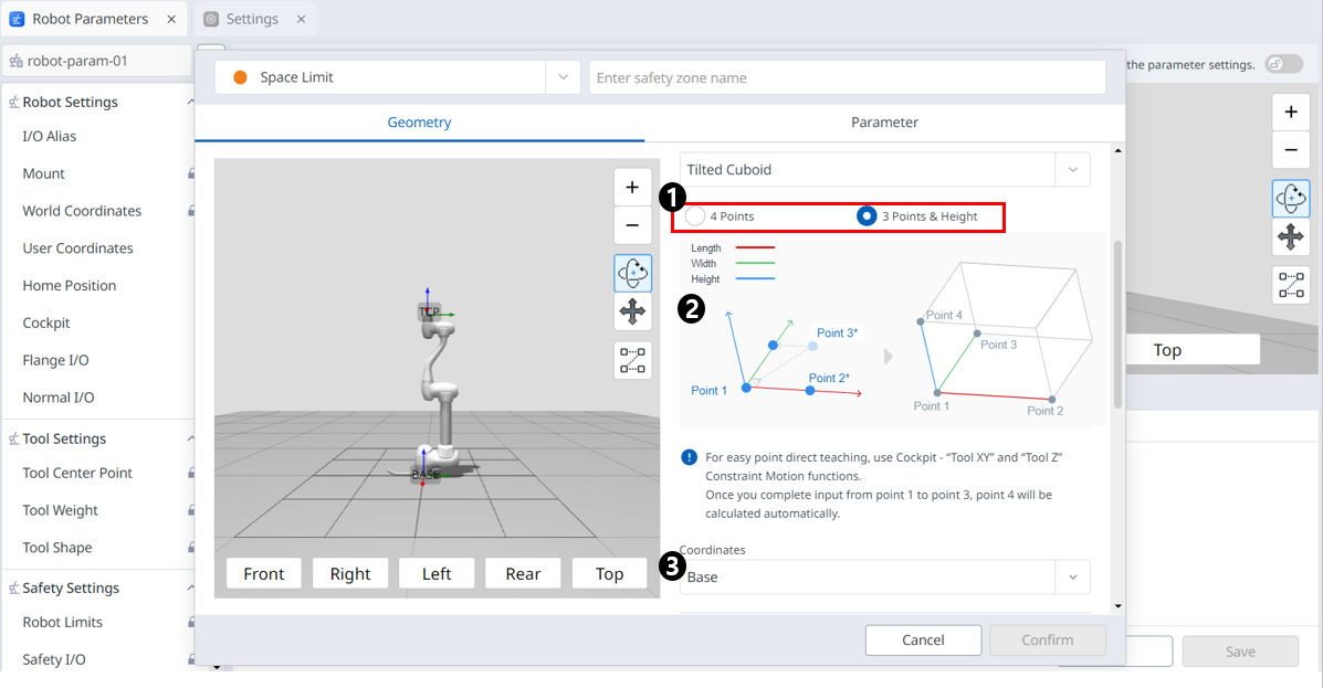
4 Points
Menu
Items | Description | |
|---|---|---|
| 1 | input method | You can choose the input method you want. |
| 2 | Space Image | This is the area where the image of the selected type is seen. |
| 3 | Coordinates | Either Base or World coordinates can be selected from this drop-down. |
| 4 | Point 1 | Each field is where the value for Point 1 is entered. |
| 5 | Point 2 | Each field is where the value for Point 2 is entered. |
| 6 | Point 3 | Each field is where the value for Point 3 is entered. |
| 7 | Point 4 | Each field is where the value for Point 4 is entered. |
| 8 | Space Expansion | This field is where the Space Expansion can be set. |
| 9 | Cancel | This button allows the setting to be canceled. |
| 10 | Confirm | This button allows you to confirm the setting. |
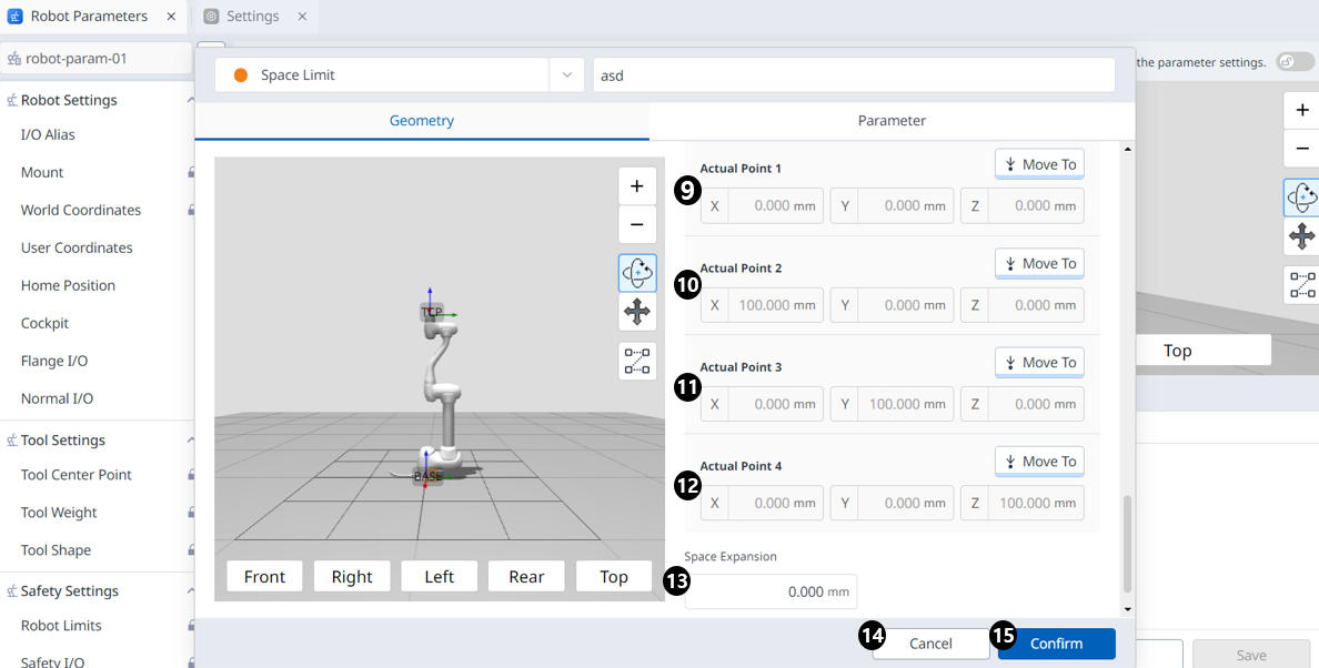
3 Points & Height
Menu
Items | Description | |
|---|---|---|
| 1 | input method | You can choose the input method you want. |
| 2 | Space Image | This is the area where the image of the selected type is seen. |
| 3 | Coordinates | Either Base or World coordinates can be selected from this drop-down. |
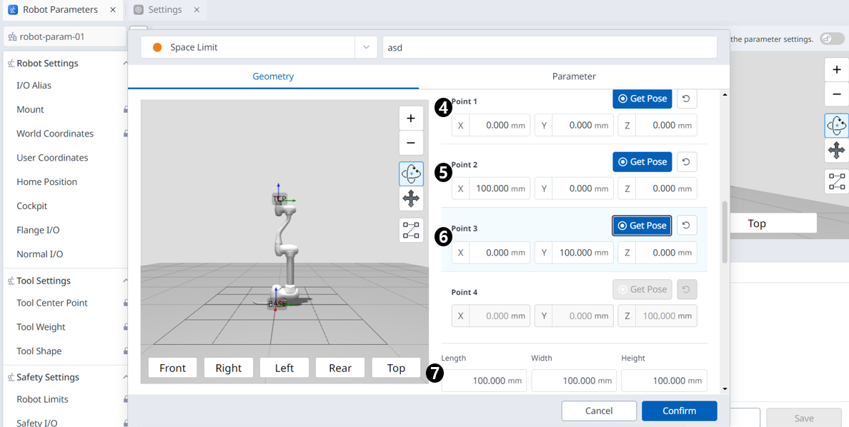
| 4 | Point 1 | Each field is where the value for Point 1 is entered. |
| 5 | Point 2 | Each field is where the value for Point 2 is entered. |
| 6 | Point 3 | Each field is where the value for Point 3 is entered. |
| 7 | size settings | Enter the Length, Width, and Height values. |
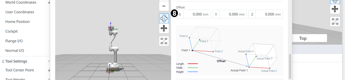
| 8 | offset settings | Enter an offset value. |
| 9 | Actual Point 1 | You can check the Actual Point 1 value calculated based on the 3 point, size, and offset information. |
| 10 | Actual Point 2 | You can check the Actual Point 2 value calculated based on the 3 point, size, and offset information. |
| 11 | Actual Point 3 | You can check the Actual Point 3 value calculated based on the 3 point, size, and offset information. |
| 12 | Actual Point 4 | You can check the Actual Point 4 value calculated based on the 3 point, size, and offset information. |
| 13 | Space Expansion | This field is where the Space Expansion can be set. |
| 14 | Cancel | This button allows the setting to be canceled. |
| 15 | Confirm | This button allows you to confirm the setting. |
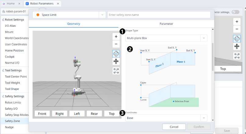
Multi-plane Box
Menu
Items | Description | |
|---|---|---|
| 1 | Shape Type | The desired Shape type can be selected from this drop-down. |
| 2 | Shape Image | This is the area where the image of the selected type is seen. |
| 3 | Coordinates | Either Base or World coordinates can be selected from this drop-down. |
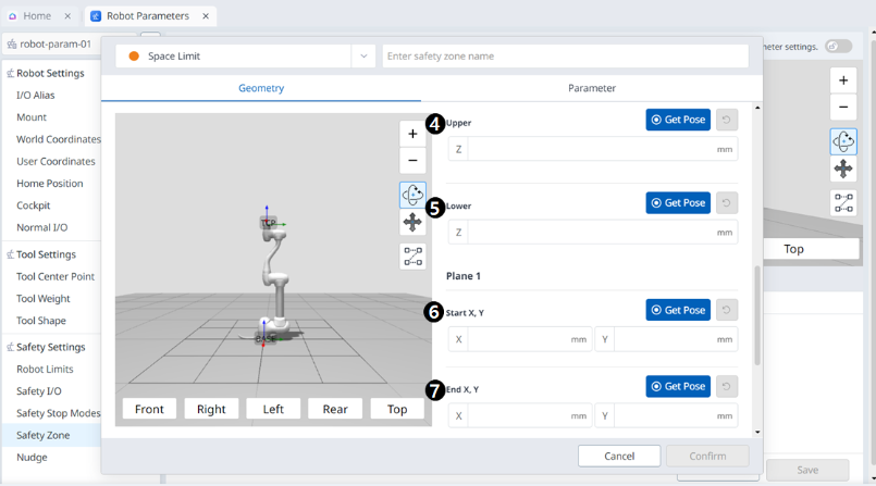
| 4 | Upper | This field is where the upper value is entered. |
| 5 | Lower | This field is where the lower value is entered. |
| 6 | Plane Start X, Y | This field is where the start point of the plane is entered. |
| 7 | Pane End X,Y | This field is where the end point of the plane is entered. |
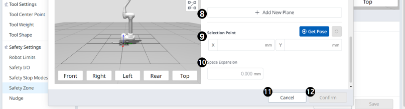
| 8 | Add New Plane | Clicking this button adds a new plane. |
| 9 | Selection Point | Each field is where the Selection Point values are entered. |
| 10 | Space Expansion | This field is where the Space Expansion can be set. |
| 11 | Cancel | This button allows the setting to be canceled. |
| 12 | Confirm | This button allows you to confirm the setting. |