What is a robot?
Functional Limits of each Robot Series
The different robot series (A, As, E, M/H, P Series) limit the use of functions as follows:
Current-based: Current of motor located on each joint is used.
FTS-based: An FTS (force torque sensor) located on the end of the robot is used.
JTS-based: JTS (joint torque sensorss) located on each joint is used.
Direct Teaching
| O | O (Current-based) | O | O | O |
Direct Teaching
| X | O (FTS based) | O | O | O |
Collision Detection | O | O (Current-based) | O | O | O |
Installation Pose Measurement | X | O (FTS based) | O | X(the robot can only be installed on the floor) | X(the robot can only be installed on the floor) |
Tool Weight Measurement | X | O (FTS based) | O | O | O |
Workpiece Weight Measurement | X | O (FTS based) | O | O | O |
Nudge Function | X | X | O | O | O |
Force Control | O (setting available only in three translation directions, excluding rotation) | O (FTS based) | O | O | O |
Compliance Control | O (setting available only in three translation directions, excluding rotation) | O (FTS based) | O | O | O |
Functional Limits of force monitoring for each Robot Series
The teach pendant and DART-Studio can be used to monitor force data. The DRL command (check_force_condition()) can also be used to externally monitor force data.
If the palletizing mode is set to “ON”: The same control/monitoring functions provided in the OFF state are available, except for H, P Series robots.
Force control | O (setting available only in three translation directions, excluding rotation) | O (FTS-based) | O | O | O |
O (If the palletizing mode is set to “ON”: Force control output limited (Base Rx, Ry orientation) 1)) | O (If the palletizing mode is set to “ON”: Force control output limited (Base Rx, Ry orientation) 1)) | ||||
Compliance control | O (setting available only in three translation directions, excluding rotation) | O (FTS-based) | O | O | O |
O (If the palletizing mode is set to “ON”: Compliance control output limited (Base Rx, Ry orientation) 1)) | O (If the palletizing mode is set to “ON”: Compliance control output limited (Base Rx, Ry orientation) 1)) | ||||
Force monitoring (Teach Pendant) | X | O (FTS-based) | O (Force value of “0” shown for the singularity section) | O (Force value of “0” shown for the singularity section) | O (Force value of “0” shown for the singularity section) |
O (If the palletizing mode is set to “ON”: 4-Degree of Freedom provided for the base (x, y, z, Rz)) | O (If the palletizing mode is set to “ON”: 4-Degree of Freedom provided for the base (x, y, z, Rz)) | ||||
Force monitoring (DART-Studio) | O (Force value of “0” shown for the singularity section) | O (FTS-based) | O (Force value of “0” shown for the singularity section) | O (Force value of “0” shown for the singularity section) | O (Force value of “0” shown for the singularity section) |
O (If the palletizing mode is set to “ON”: 4-Degree of Freedom provided for the base (x, y, z, Rz)) | O (If the palletizing mode is set to “ON”: 4-Degree of Freedom provided for the base (x, y, z, Rz)) | ||||
Force monitoring (When using DRL commands: | O (Force value of “0” shown for the singularity section) | O (FTS-based) | O (Force value of “0” shown for the singularity section) | O (Force value of “0” shown for the singularity section) | O (Force value of “0” shown for the singularity section) |
O (If the palletizing mode is set to “ON”: 4-Degree of Freedom provided for the base (x, y, z, Rz)) | O (If the palletizing mode is set to “ON”: 4-Degree of Freedom provided for the base (x, y, z, Rz)) |
Control output limit (Base Rx, Ry orientation): The force or compliance control values corresponding to the The force or compliance control values corresponding to the Base Rx, Ry orientation are not output. Entering the force or compliance control value of the relevant axis (Base Rx, Ry) will be ignored as “0”.
Overview of Singularity
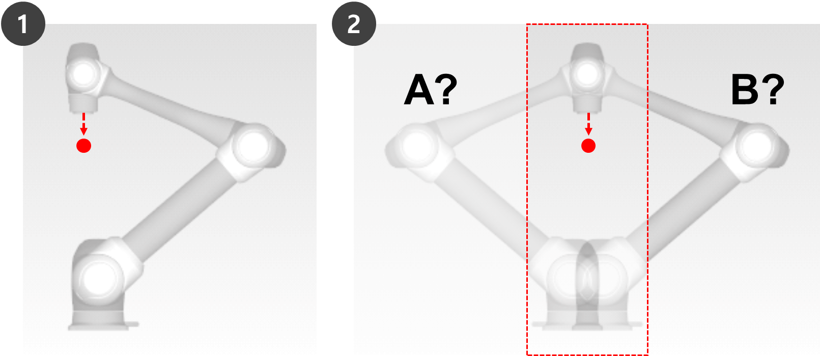
Singularity in a multi-joint robot refers to a position (or point in a multi-joint robot refers to a position (or point) where the robot has difficulty in calculating its next pose during moving. Multi-joint robots calculate each joint angle during movement based on the robot end.
For example, in Fig. 1 below, when the robot is moving to the red dot, the robot will not be able to determine whether to move its joints to set pose A or pose B as shown in Fig. 2. This position (or point) is called the singularity.
Near a singularity, robot movement is not fluid in terms of plane, point and line, robot end linear movement may not be maintained, and position error during control may increase. Singularity occurs in 3 cases as shown in the following figure, including when the robot joints form a line.
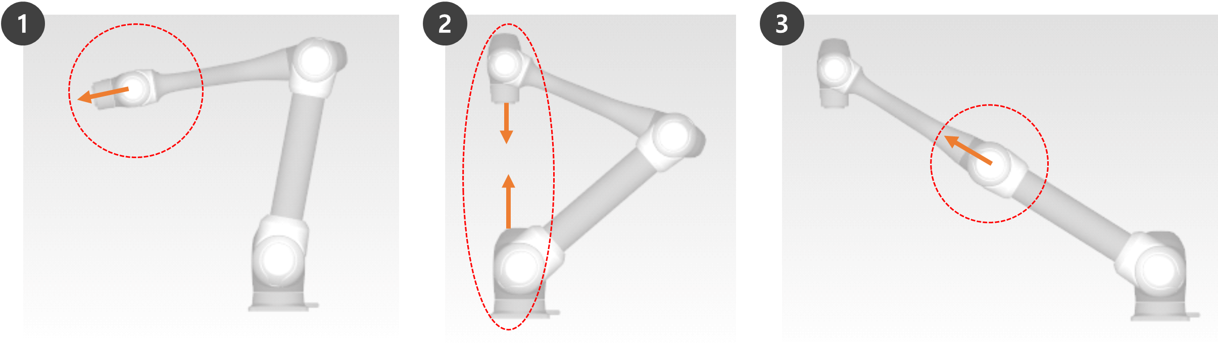
Wrist Singularity: When the robot wrist forms a line as Axis 5 approaches 0º
Shoulder Singularity: When Axes 1 and 6 are on the same line
When compared to a human arm, Axes 1 and 2 correspond to the shoulder joint.
Elbow Singularity: When the robot forms a line as Axis 3 approaches 0º
When compared to a human arm, Axis 3 corresponds to the elbow.
Manual and automatic operations moving with joint rotation are not influenced by singularity.
Task movement, MoveL command, etc.
Singularity only occurs during manual and automatic operation where the robot ends performing linear movement.
Joint movement, MoveJ commands, etc.
In the singularity zone, force control or compliance control is unavailable.
As the rotation speed of certain axes increase rapidly when a linear motion passes a singularity, it is possible for a Joint Speed Limit Violation or Joint Angle Limit Violation to occur.
How to avoid Singularity
Doosan Robotics robots provide options to avoid singularities during motion control. However, it is recommended to configure a task that does not create exceptions using joint movement commands such as MoveJ in singularity zones.
Here are the singularity avoidance options provided by Doosan Robot:
Automatic avoidance: Performs motion by avoiding singularities. However, the robot motion may differ from the expected path.
Path priority: Maintains path and speed, but may stop due to an error near a singularity.
Variable speed: Maintains path, but decelerates near a singularity.
Overview of Euler Angle
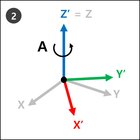
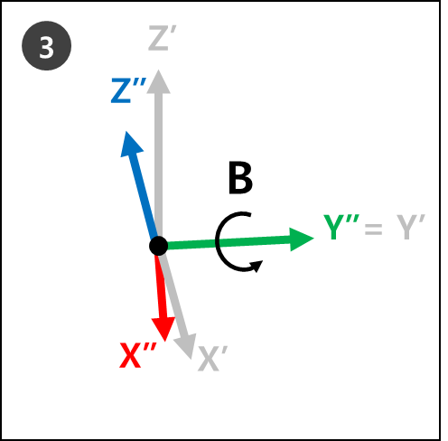
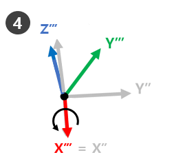
Euler Angle is a way to express the angles of X, Y and Z axes, which are perpendicular among themselves in the object direction. A, B and C refer to the sequential rotation angles. Each robot manufacturer defines this A, B and C rotation order differently, such as Rz-Ry-Rz, Rz-Ry-Rx or Rx-Ry-Rz.
For example, Rz-Ry-Rx. Here, Rz means the rotation in Z-axis, Ry means the rotation in Y-axis and Rx means the rotation in X-axis. Rz can be expressed as angle A, Ry as angle B, and Rx as angle C to indicate the current rotating direction of an object. Note that once rotation is made in Z-axis direction from the coordinates, rotations will be made based on new coordinates.
This can be visualized with steps 1 to 4.
 |  |
 |  |
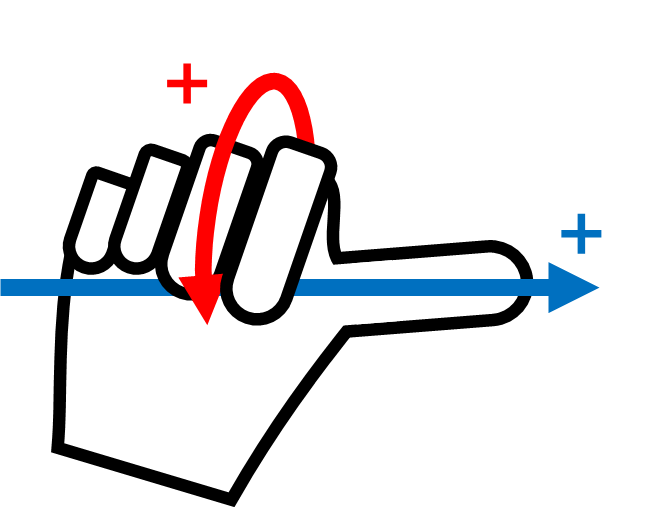
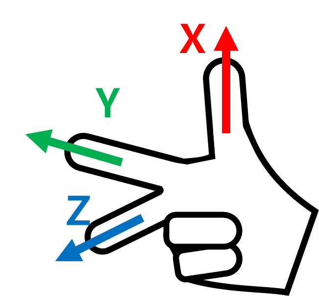
This can be easily visualized with one’s right hand. Make the following pose with your right hand. This is called the Right-Hand Rule, and making the thumb (X-axis), index finger (Y-axis) and middle finger (Z-axis) to be perpendicular to each other will create coordinates consisting of X, Y and Z axes.
Then make the Right-Hand Rule Cartesian pose and make rotations Rz, Ry and Rx in sequential order.
Ry: Rotate the index finger (Y-axis) by B degrees.
Rx: Rotate the thumb (X-axis) by C degrees.
The + rotating direction of The + rotating direction of A, B and C is the direction of four fingers except the thumb, when the thumb is pointing at the + direction and the four fingers are clenched. This is called the Law of Clockwise Screw.