
Signal from Robot to Welding Machine (Robot to Machine)
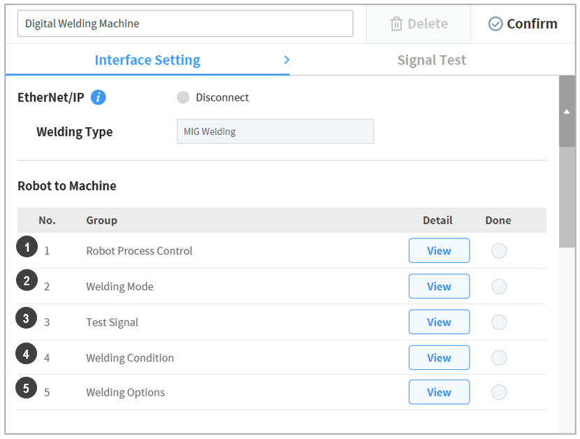
Sets the signals sent from the robot to the welding machine. From the image below, set the ➊Robot Process Control, ➋Welding Mode, ➌Test Signal, ➍Welding Condition, and ➎Welding Options Signal settings.
| No. | Item | Description |
|---|---|---|
1 | Robot Process Control | (Including mandatory settings) One of the signals sent from the robot to the welding machine, this sets the signals used to link to the robot-welding machine during welding. This includes the Welding Start, Robot Ready, and Error Reset signals. |
2 | Welding Mode | This sets the welding mode and working mode signals, and it can also set mode signals supported by the welding machine. For more information about specific modes, refer to the corresponding welding machine manual.
|
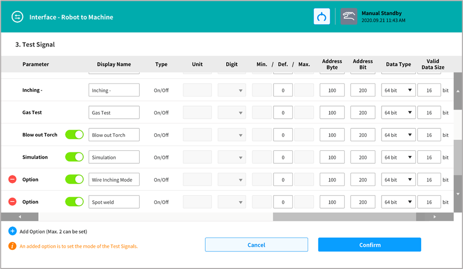
3 | Test Signal | (Including mandatory settings) This sets the wire inching (+/-) (inching +, inching -), protective gas test (gas test), clean torch (blow out torch) and weld simulation mode (simulation) signals. It can be set by adding two additional items. |
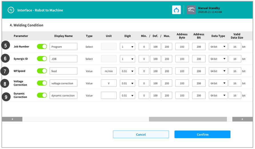
4 | Welding Condition | Select the synergic condition number and welding job number saved in the welding machine, then set a signal that can adjust specific conditions during welding. This includes the welding job number (Job Number), synergic condition number (Synergic ID), wire feeding speed (WFSpeed), voltage correction (Voltage Correction) and dynamic property correction (Dynamic Correction). |
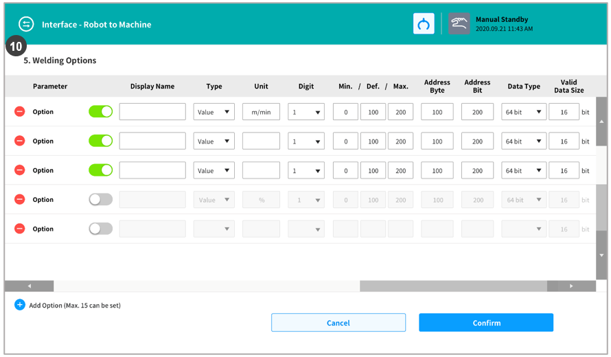
5 | Welding Options | It can be set by adding necessary items. Up to 15 items can be added. |
Note
If a mandatory setting items for each group is not set, the Signal Test tab cannot be accessed.
EtherNet/IP interface setting items can be set in advance. Set items are automatically set and displayed when setting welding conditions.
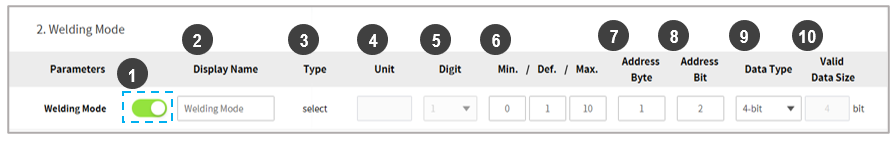
It is possible to set the display name, type, unit, digit, min./def./max., address byte, address bit, data type, valid data size, and enablement status.
| No. | Item | Description |
|---|---|---|
1 | Enable Button | Sets the enable/disable status of the corresponding item. Mandatory items of each group do not feature this button. |
2 | Display Name | Sets the name displayed when the corresponding item is used in a welding condition setting, etc. As the names used in welding machines differ from each other, this allows the name of the function used in the welding machine to be set. Up to 20 alphabet characters can be entered. |
3 | Type | Sets the input type of the function.
|
4 | Unit | Sets the range of the function. |
5 | Digit | Sets the decimal place of the entered value. (1 / 0.1 / 0.01) |
6 | Min./Def./Max | Sets the min./max. value. |
7 | Address Byte | Sets the start pose of data for communication. |
8 | Address Bit | Sets the start pose of data for communication. |
9 | Data Type | Sets the size of the communication data. (1-bit (disable Low), 1-bit (disable high), 2-bit, 4-bit, 8-bit (byte), 15-bit, 16-bit (short), 32-bit (int)) |
10 | Valid Data Size | Sets the valid data size. |
Note
The names and setting methods of the above welding conditions may vary according to each welding machine. Set and use items by referring to the datasheet of each welding machine.
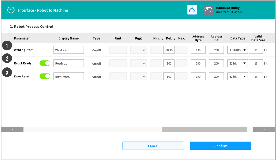
Group 1) Welding Process Control Signals (Robot Process Control)
| No. | Item | Description |
|---|---|---|
1 | Welding Start | Welding Start |
2 | Robot Ready | Robot Ready |
3 | Error Reset | Error Reset signals |
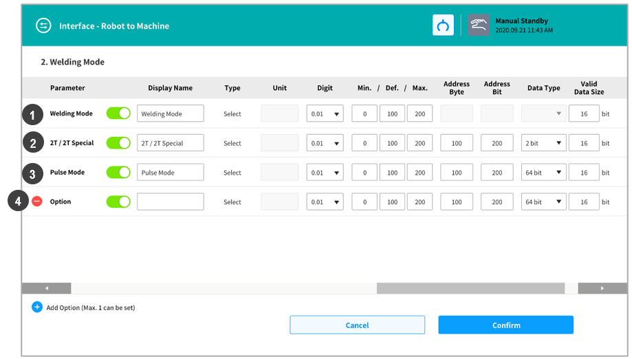
Group 2) Welding Modes
| No. | Item | Description |
|---|---|---|
1 | Welding Mode | This designates a welding mode setting unique to the welding machine. For example, it corresponds to the working mode of “Fronius” welding machines. |
2 | Latched/Non-Latched Mode | This is the signal used to set a working mode unique to the welding machine. It mainly sets the weld start/end condition (2T/2T Special). For example, it corresponds to the operating mode (latched/non-latched mode) of “EWM” welding machines. |
3 | Pulse Mode | This designates the pulse welding mode enablement status. |
4 | Option Mode | This can be used to add an item that requires a mode change, other than the designated items in basic mode. |
Group 3) Test Signals
Group 4) Welding Condition Settings (Welding Condition)
| No. | Item | Description |
|---|---|---|
5 | JOB Number | This designates the JOB number corresponding to the welding condition saved in the welding machine. |
6 | SYNERGIC Number | This designates the number of the program with the saved welding condition for linking with the synergic function provided by the welding machine. |
7 | Feeding Speed Correction | This designates the wire feeding speed value. |
8 | Voltage Correction | This designates the voltage correction value during welding. |
9 | Dynamic Variable Correction | This designates the dynamic variable correction value during welding. |
Group 5) Other Option Signals (Welding Options)
| No. | Item | Description |
|---|---|---|
10 | Option 1 - Option 15 | This can be used to designate items other than the basic welding condition items that require welding conditions. |