
Installation (CS-12P)
Cautions during Installation
Caution
- Secure sufficient space before installing the controller. If not enough space is secured, the controller may be damaged or the manipulator or teach pendant cable may have a shortage.
- Check the input power supply when connecting power to the product. If the connected input power supply is different from the rated power input (22-60VDC), the product many not operate properly or the controller may be damaged.
Installation Environment
When installing the controller, consider the following.
- Secure sufficient space before installing the controller.
- The controller must be fixed.
- Make sure no component is not fixed in the mobile vehicle.
Hardware Installation
Install the robot, controller and teach pendant, the key components of the system, and supply power to them before operating the manipulator. Installation of each component is as follows:
Connecting the Manipulator and Controller
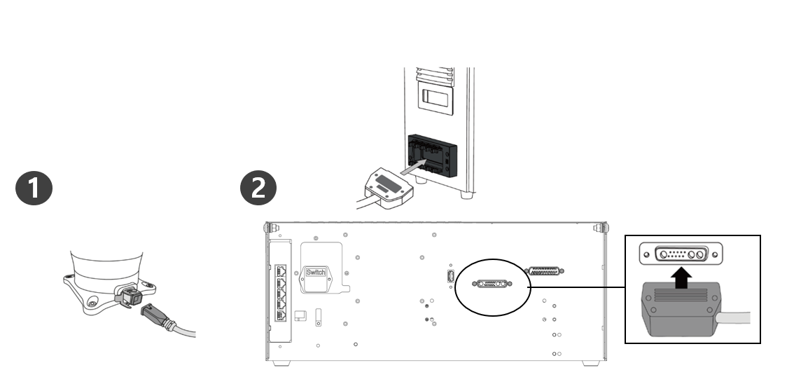
| 1 | Connect the manipulator cable to the controller, place a securing ring
|
| 2 | Connect the manipulator cable’s opposite end to the controller connector
|
Caution
- Do not disconnect the robot cable while the robot is turned on. This can cause damage to the robot.
- Do not modify or extend the robot cable.
- When installing the controller in the mobile vehicle, secure at least 50 mm of space on each side of the controller to enable ventilation.
- Make sure that connectors are properly connected before turning on the controller.
Note
- When configuring the system, it is recommended that a noise reducer be installed to prevent noise effects and malfunction of the system.
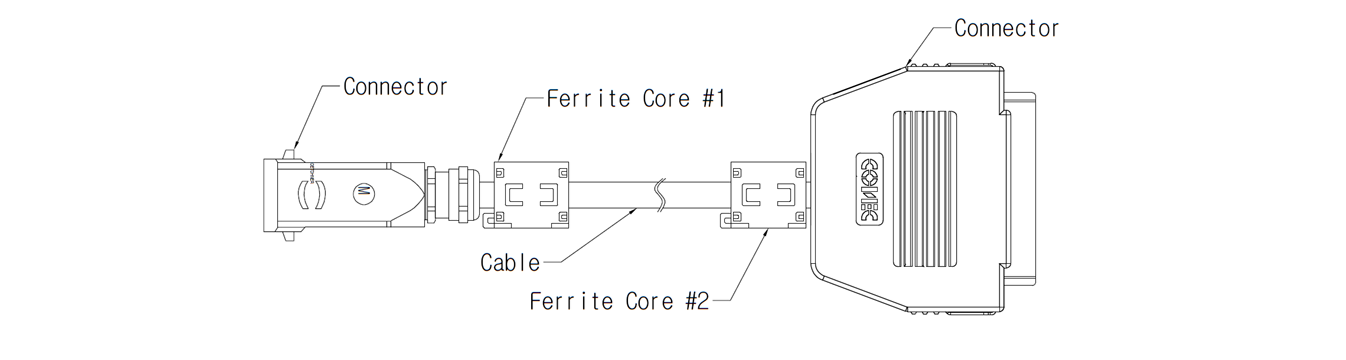
- If the controller is influenced by noise generated by electromagnetic waves, it is necessary to install a ferrite core to ensure normal operation. The installation location is as follows:
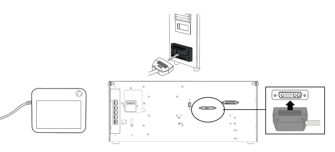
Connecting the Controller and Teach Pendant
Push the teach pendant cable into the corresponding controller connector until a click is heard to prevent the cable from becoming loose.
Caution
- Make sure that the pins of the cable end are not damaged or bent before connecting the cable.
- If the teach pendant is used by hanging on the mobile vehicle or on the controller, be careful not to trip on the connecting cables.
- Be careful not to allow the controller, teach pendant and cable come in contact with water.
- Do not install the controller and teach pendant in a dusty or wet environment.
- The controller and teach pendant must not be exposed to a dusty environment. Be especially careful in environments with conductive dust.
Note
- When configuring the system, it is recommended that a noise reducer be installed to prevent noise effects and malfunction of the system.
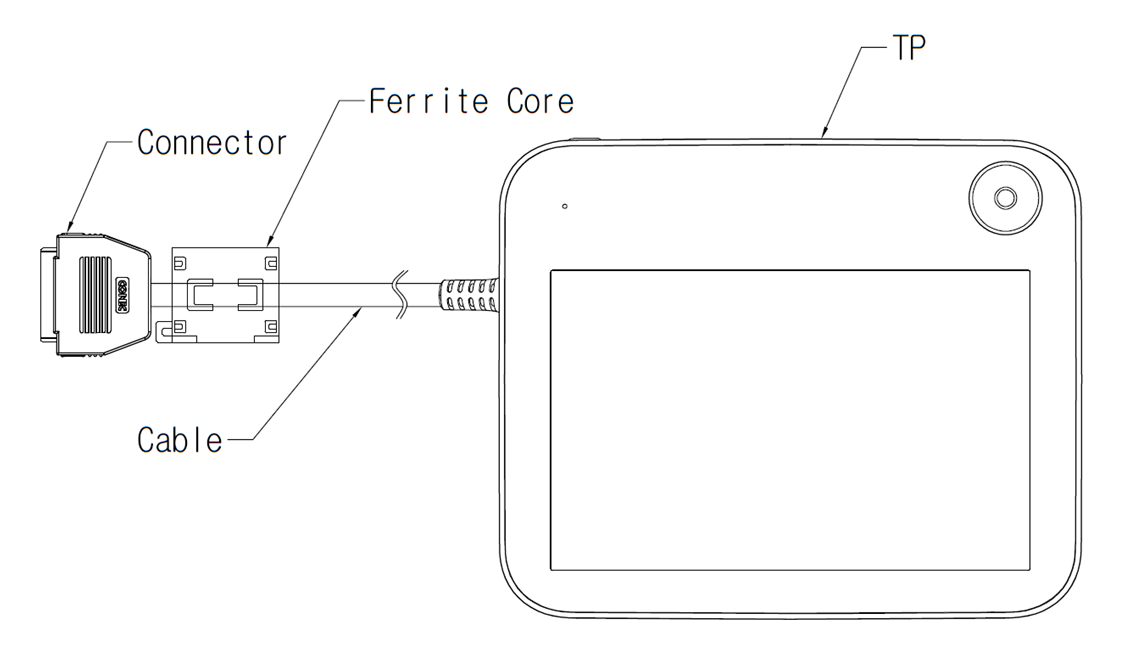
- If the teach pendant is influenced by noise generated by electromagnetic waves, it is necessary to install a ferrite core to ensure normal operation. The installation location is as follows:
Routing of Manipulator Cable and Teach Pendant Cable
Ensure that the manipulator and teach pendant cable curvature radius is greater than the minimum curvature radius (120 mm).
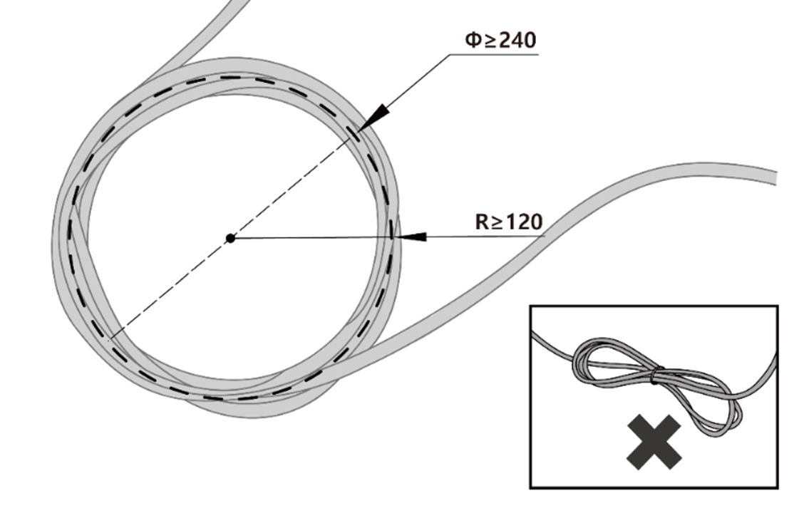
Caution
- Ensure that the curvature radius between the teach pendant cable and teach pendant connector is greater than the minimum curvature radius (120 mm).
- If the curvature radius is smaller than the minimum curvature radius (120 mm), cable disconnection or product damage may occur.
- In environments where electromagnetic noise can occur, proper cable installation must be taken to prevent malfunctions.
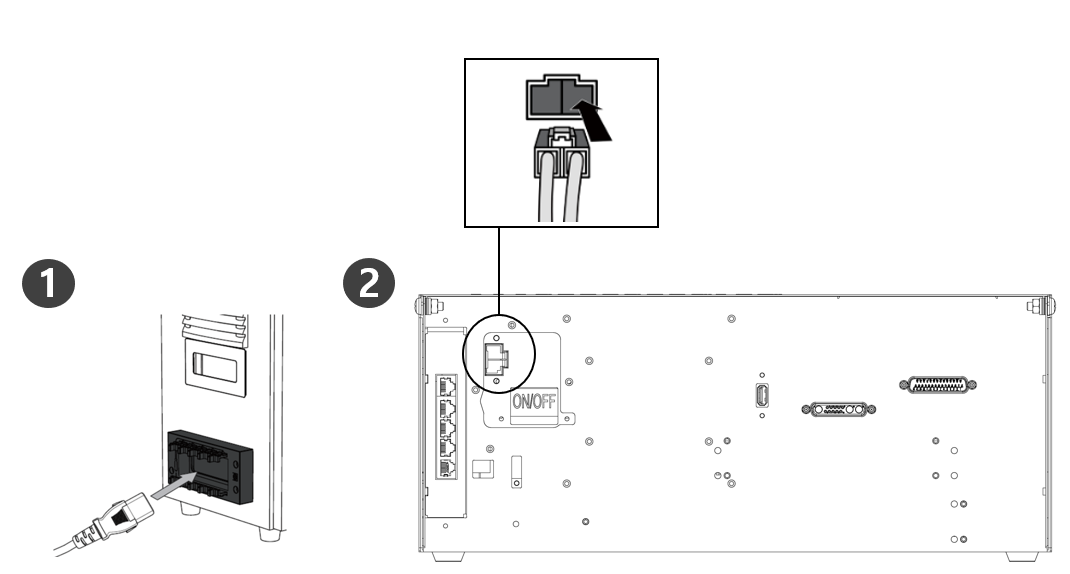
Supplying Power to the Controller
Push the power cable into the corresponding controller connector until a click is heard to prevent the cable from becoming loose.
Warning
- After connecting the power cable, make sure that the robot has established a proper ground (electronic ground connection). Establish a common ground for all equipment in the system with an unused bolt related to the ground symbol inside the controller. The ground conductor must satisfy the maximum current rating of the system.
- Protect the input power of the controller using devices such as a circuit breaker.
- Do not modify or extend the robot cable. It can cause fire or controller breakdown.
- Make sure that all cables are properly connected before supplying power to the controller. Always use the original cable included in the product package.
- Be careful not to connect the polarity of the input voltage incorrectly.
Note
- When configuring the system, it is recommended to install a power switch that can turn off power to all devices in the system at once.
- If a controller for the AGV is used, the robot’s movement may be limited according to the load and motion.
- If the input voltage is less than 48V, the robot’s movement may be limited according to the load and motion.
- The power supply must satisfy minimum requirements such as ground and circuit breakers. The electrical specifications are as follows:
Parameter | Specification |
Input Voltage | 22 – 60 VDC |
Rated Input Current | 30 A |