
Flange Digital Output Specifications
Flange digital output is a PNP specification, and photo coupler output is set up in the output.
The corresponding output channel becomes +24V when digital output is activated. The corresponding output channel becomes open (floating) when digital output is deactivated.
The electrical specifications of the digital output are as follows:
Parameter | Min | Typ | Max | Unit |
|---|---|---|---|---|
Voltage when driving 10mA | 23 | - | - | V |
Voltage when driving 50mA | 22.8 | - | 23.7 | V |
Current when driving | 0 | - | 50 | mA |
The setting has been charged as follows since April 11, 2024
Digital Outputs support two different modes:
| Mode | Active | Inactive |
|---|---|---|
| PNP (Source Type, default) | High | Open |
| NPN (Sink Type) | Low | Open |
Digital Outputs initial power is set to 0V, and can be set to 12V or 24V.
When digital output is disabled, the state of the corresponding output channel is open (floating).
The electrical specifications are shown below:
Parameter | Min | Typ | Max | Unit |
|---|---|---|---|---|
Voltage when driving 12V mode | 11.4 | 12 | 12.6 | V |
Voltage when driving 24V mode | 22.8 | 24 | 25.2 | V |
Current when driving | 0 | - | 50 | mA |
Caution
- Digital output is not subject to current limitation. Ignoring the specifications presented above during operation may cause permanent damage to the product.
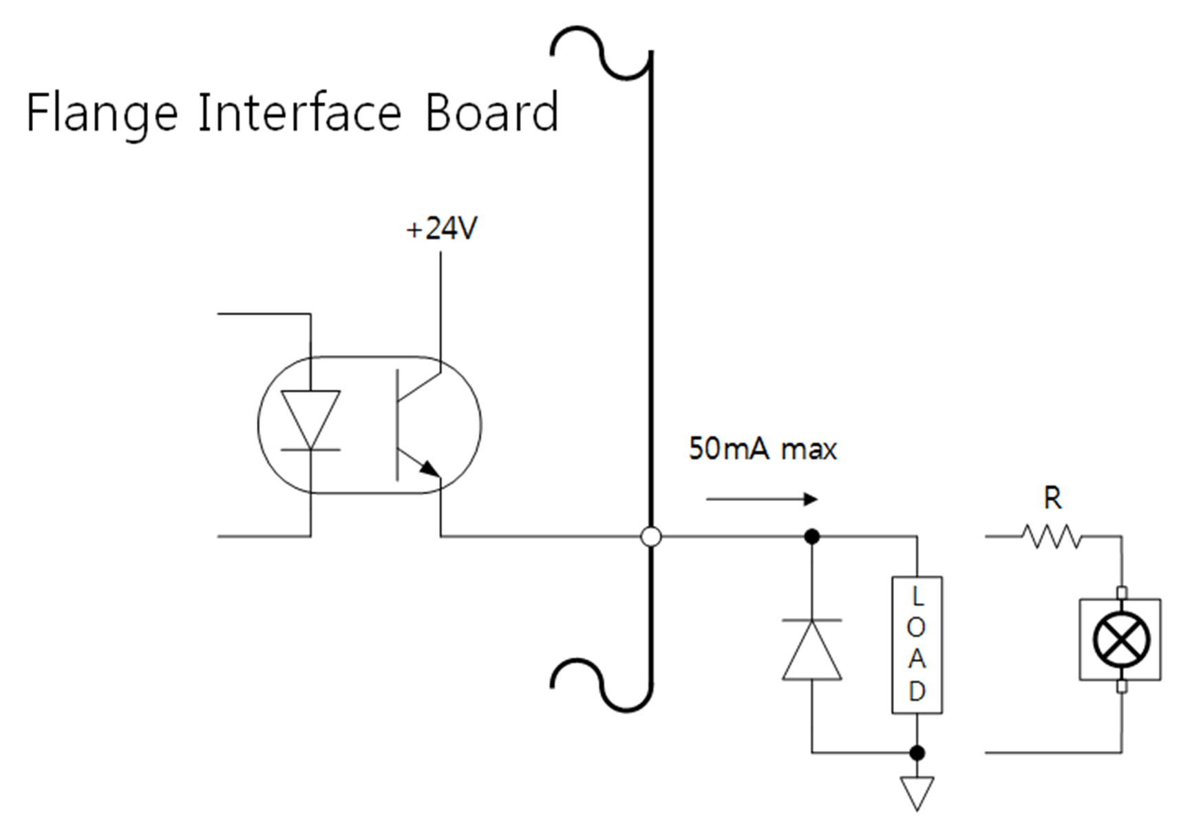
- The figure below is an example of a digital output setup, so refer to it while connecting the tool and gripper.
- Make sure to disconnect the power from the robot when setting up the circuit.