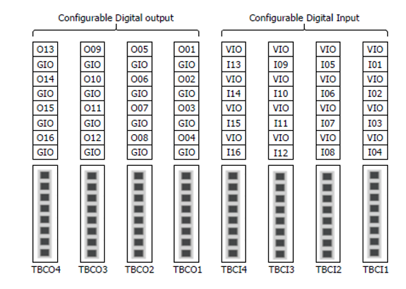
Configuring Configurable Digital I/O (TBCI1 - 4,TBCO1 - 4)
The controller is configured with 16 digital inputs and 16 digital outputs. The digital I/Os shown in the figure below can be connected to peripherals required for robot control, or can be set as redundant Safety IOs to be used as safety signal I/O purposes.
The electrical specifications of the #configurable# digital I/O are as follows:
#Terminal# | Parameter | Specifications | |
|---|---|---|---|
Digital Output | [Oxx] | Voltage | 0 - 24 V |
[Oxx] | Current | 0 - 1 A | |
[Oxx] | Voltage Drop | 0 - 1 V | |
[Oxx] | Leakage Current | 0 - 0.1 mA | |
Digital Input | [Ixx] | Voltage | 0 - 30 V |
[Ixx] | OFF Range | 0 - 5 V | |
[Ixx] | ON Range | 11 - 30 V | |
[Ixx] | Current | 2 – 15 mA | |
Caution
- The VIO (IO 24V) and GIO (IO GND) terminals, which can be used as power supplies for digital I/O, are separated from the other power supplies, VCC (24V) and GND, on the safety I/O circuit. Use caution, as the diagnostic functions of the robot will detect errors and cut off the power to the robot if the internal power supply is connected as a digital I/O power supply through the Terminal Block for Digital I/O Power (TBPWR) or if the 24V power is not supplied to the VIO and GIO terminals through an external power supply, the configurable digital I/O will not operate.
When configurable digital I/O is used as a general digital I/O, it can be used in various ways such as operating low-current equipment such as solenoid valves for voltage or exchanging signals with PLC systems or peripherals. The following is how to use the configurable digital I/O:
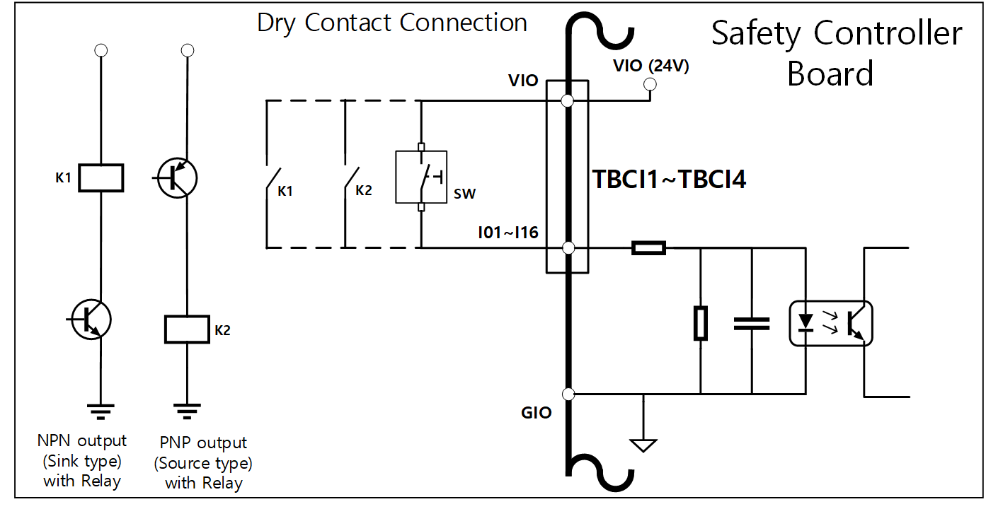
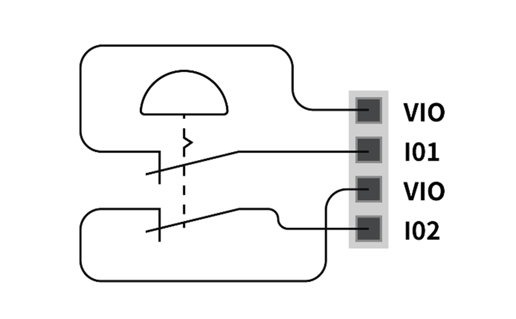
If #dry contact# input is received
This is a method of connecting a #switch# or #contact# between the VIO terminal of terminal blocks TBCI1-TBCI4 and Ixx terminals. The output of the external device only acts on the #open/close# of the contact through the relay, so it is electrically insulated from external devices.
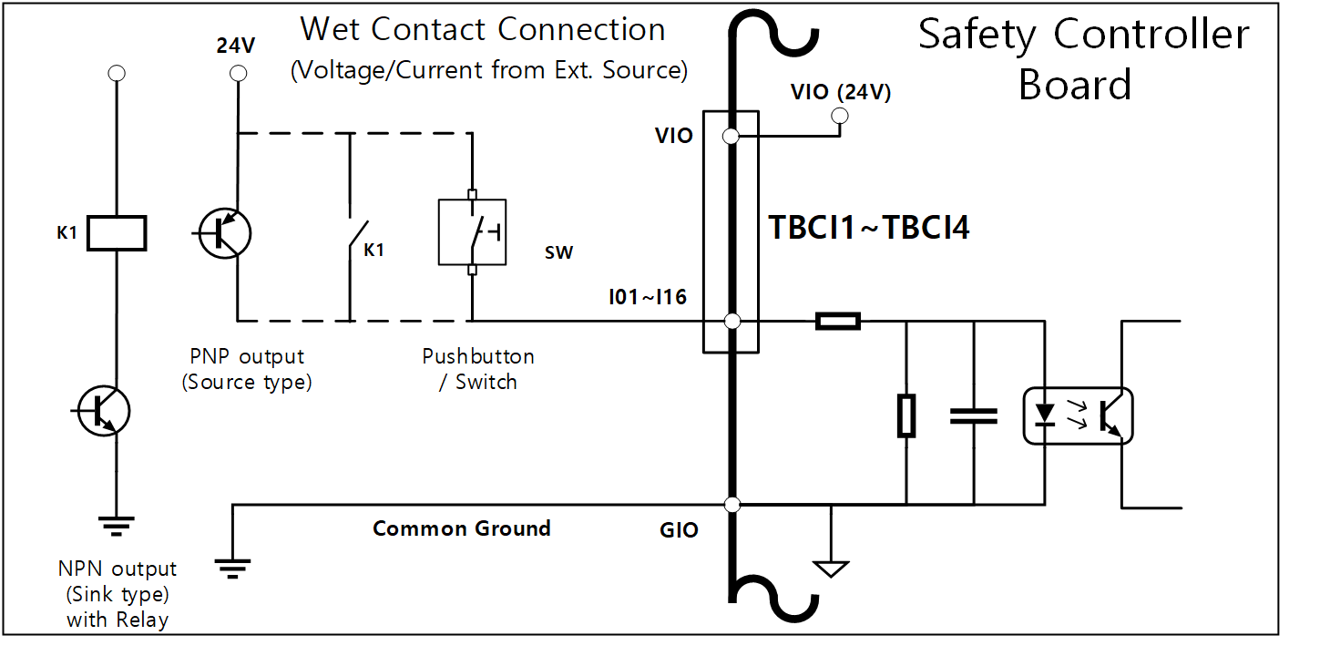
If #wet contact# input is received
It receives voltage-type signals from external devices. If the output of the target device is source type, it receives a voltage of 24V/0V as input. If the output of the target device is #sink type#, a relay can be added to receive voltage of 24V/0V as input. Because voltage input requires a reference, the external devices and the external power supply must be connected to a common #ground#.
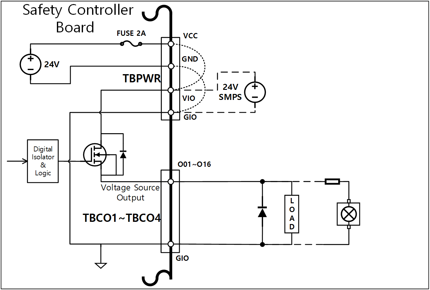
If a simple load is operated
It is a method of connecting loads between Oxx terminals of TBCO1-TBCO4 terminal blocks and the GIO terminal. Each terminal is capable of outputting a maximum of 1A, but the overall current may be limited according to the calorific value and load.
If digital I/O power (VIO/GIO) is supplied through the internal power supply as in the factory default setting, up to 2A of VIO current can be used. If a total current greater than 2A is required, remove the connection between the digital I/O power supply (VIO/GIO) of the Terminal Block for Digital I/O Power (TBPWR) and the internal power supply (VCC/GND) and connect an external power supply.
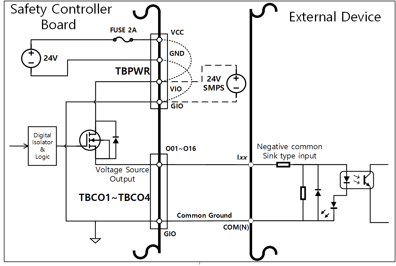
If a #negative common & sink type# input device is connected
When connecting the output of the digital IO to a sink-type input device, connect the Oxx terminals of TBCO1 - TBCO4 terminal blocks to the input terminal of the external device, and connect GIO to the negative common of the external device to establish a common ground.
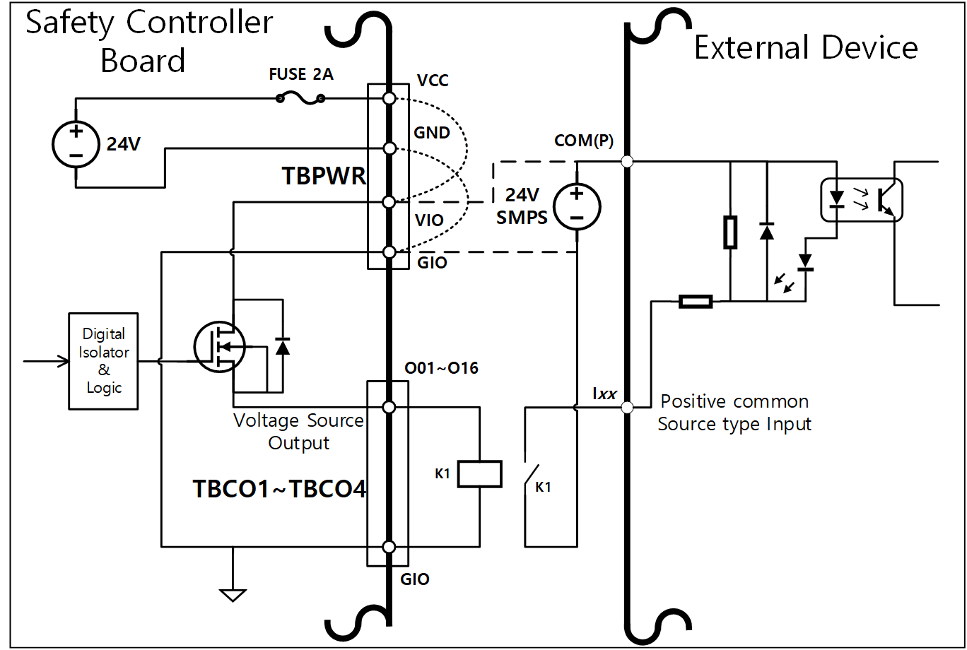
If a #positive common & source type# input device is connected
Connect a relay between the Oxx terminal of TBCO1-TBCO4 terminal blocks and the GIO terminal to supply input signals as contacts to the external device. If necessary, an external power supply can be connected to the external device.
Caution
- The operation of the general digital IO devices can be interrupted at any time by cutting off the power to the controller, detecting errors by self-diagnosis, and settings of the task program. Therefore, perform a risk assessment before configuring the robot work cell and be sure to implement additional safety measures if additional risks, such as falling of the workpiece, stopping, negligence of the digital input due to digital outputs being switched off or synchronization errors due to misunderstanding, are foreseen.
- The #general# digital I/O is a single connection type I/O and any short circuits or breakdown can result in the loss of safety functions, so it cannot be used for safety purposes. If the connection of a safety device or safety-related signal I/O is required, be sure to set the corresponding terminal as redundant Safety I/O on the teach pendant.
When configurable digital IO is used as Safety IO
O01 & O02, … , O15 & O16, I01 & I02, .. I15 & I16, can use identical safety signals to form a dual safety I/O.
The dedicated input terminal of the Safety Contact Output Terminal (TBSFT) can only connect a dry contact signal, but the input set as Safety IO can connect both contact-type (dry contact) and voltage-type (wet contact) signals. The output set to Safety I/O outputs voltage, but if necessary, a relay can be added externally to configure a contact type output.
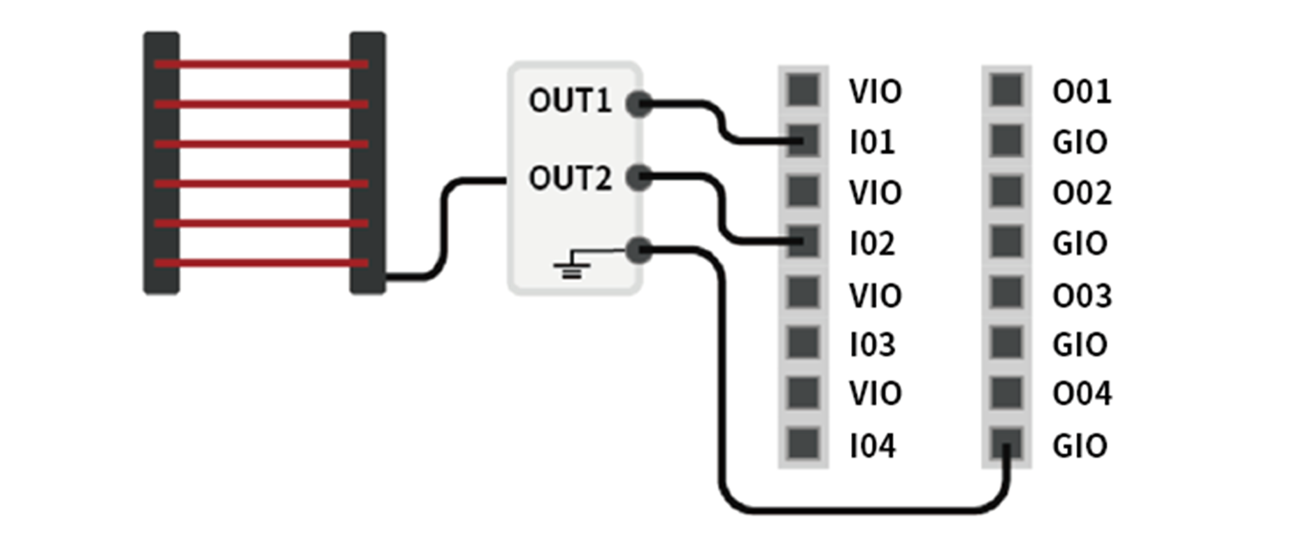
The following is an example of connecting a safety device for operation.
- Connect a contact type (Dry Contact) signal emergency switch as a safety input terminal
- Connect a voltage type (Wet Contact) signal light curtain as a safety input terminal (common ground)