
Flange I/O
The end flange cover of the robot has two M8 spec 8-pin connectors, and refer to the figure below for the location and shape.
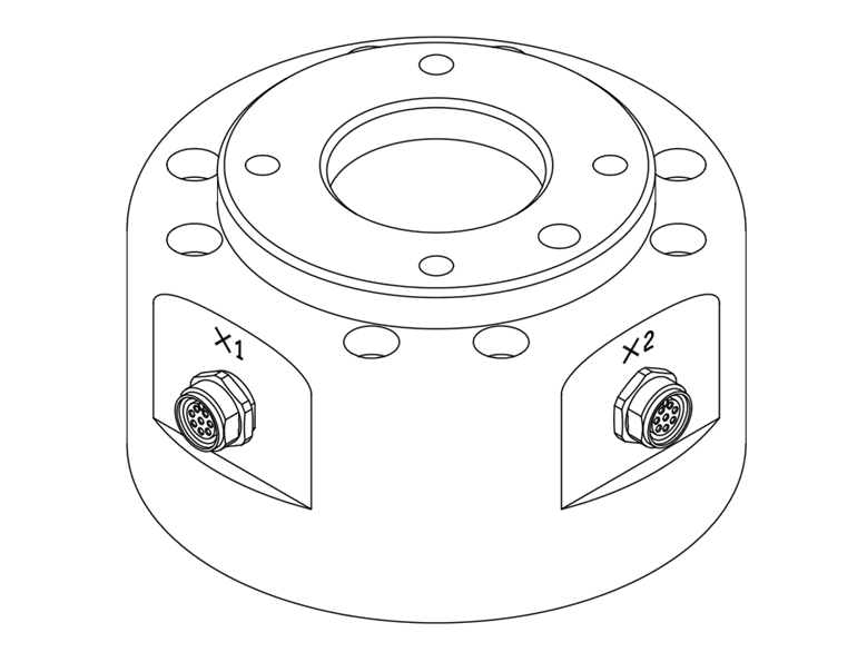
The connector supplies power and control signals necessary to operate the gripper or sensors embedded within specific robot tools. The following are sample industrial cables (equivalent cables can be used):
- Phoenix contact 1404178, male (Straight)
- Phoenix contact 1404182, male (Right Angle)
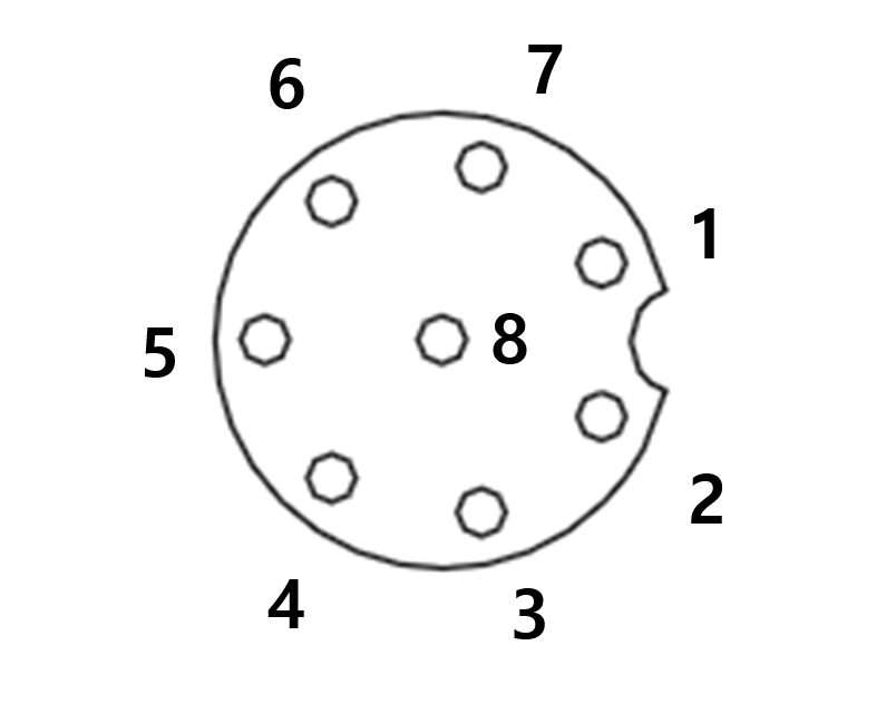
The pin map of each connector is as follows:
Schematic Diagram
products manufactured from August 2022, the connector orientation has been changed as shown in the figure below.
I/O functions provided through X1 and X2 connectors are different from each other, and refer to the table below for detailed I/O settings.
X1 Setting (Digital IN/OUTPUT)
No | Signal type | Description |
|---|---|---|
1 | Digital Input 1 | PNP (Source Type, default) |
2 | Digital Output 1 | set to either PNP (Source Type, default) or NPN (Sink Type) |
3 | Digital Output 2 | set to either PNP (Source Type, default) or NPN (Sink Type) |
4 | Digital Output 3 | set to either PNP (Source Type, default) or NPN (Sink Type) |
5 | Power | +24V |
6 | Digital Input 3 | PNP (Source Type, default) |
7 | Digital Input 2 | PNP (Source Type, default) |
8 | GND |
X2 Setting (Digital IN/OUTPUT)
No | Signal type | Description |
|---|---|---|
1 | Digital Input 4 | PNP (Source Type, default) |
2 | Digital Output 4 | set to either PNP (Source Type, default) or NPN (Sink Type) |
3 | Digital Output 5 | set to either PNP (Source Type, default) or NPN (Sink Type) |
4 | Digital Output 6 | set to either PNP (Source Type, default) or NPN (Sink Type) |
5 | Power | +24V |
6 | Digital Input 6 | PNP (Source Type, default) |
7 | Digital Input 5 | PNP (Source Type, default) |
8 | GND |
Internal power of flange I/O is set to 24V, and refer to the table below for detailed power specifications during I/O connection
Parameter | Min | Typ | Max | Unit |
|---|---|---|---|---|
Supply voltage | - | 24 | - | V |
Supply current | - | - | 3 | A |
Digital output | - | 6 | - | EA |
Digital input | - | 6 | - | EA |
The setting has been charged as follows since March 22, 2024
X1 Setting
No | Signal type | Description |
|---|---|---|
1 | Digital Input 1 | PNP (Source Type, default) |
2 | Digital Output 1 | set to either PNP (Source Type, default) or NPN (Sink Type) |
3 | Digital Output 2 | set to either PNP (Source Type, default) or NPN (Sink Type) |
4 | Analog Input 1 / RS-485 + | set to either Voltage (0-10V) or Current (4-20mA, default) / |
5 | Power | Set the internal power supply to +24V (default), +12V or 0V |
6 | Analog Input 2 / RS-485 - | set to either Voltage (0-10V) or Current (4-20mA, default) / |
7 | Digital Input 2 | PNP (Source Type, default) |
8 | GND |
X2 Setting
| No | Signal type | Description |
|---|---|---|
| 1 | Digital Input 3 | PNP (Source Type, default) |
| 2 | Digital Output 3 | set to either PNP (Source Type, default) or NPN (Sink Type) |
| 3 | Digital Output 4 | set to either PNP (Source Type, default) or NPN (Sink Type) |
| 4 | Analog Input 3 / RS-485 + | set to either Voltage (0-10V) or Current (4-20mA, default) / Max 1M baud rate |
| 5 | Power | Set the internal power supply to +24V (default), +12V or 0V |
| 6 | Analog Input 4 / RS-485 - | set to either Voltage (0-10V) or Current (4-20mA, default) / Max 1M baud rate |
| 7 | Digital Input 4 | PNP (Source Type, default) |
| 8 | GND |
Set the internal power supply to 24V, 12V or 0V.
The electrical specifications are shown below:
| Parameter | Min | Type | Max | Unit |
|---|---|---|---|---|
| Supply voltage (12V mode) | 11.4 | 12 | 12.6 | V |
| Supply voltage (24V mode) | 22.8 | 24 | 25.2 | V |
| Supply current | - | - | 3 | A |
Warning
- Set up the tool and gripper so that they do not cause any hazards when power is cut off.
(e.g., workpiece falling from the tool) - The No. 5 terminal of each connector outputs 24V at all times while power is supplied to the robot, so make sure to cut the power supply to the robot when setting up the tool and gripper.