
Flange I/O
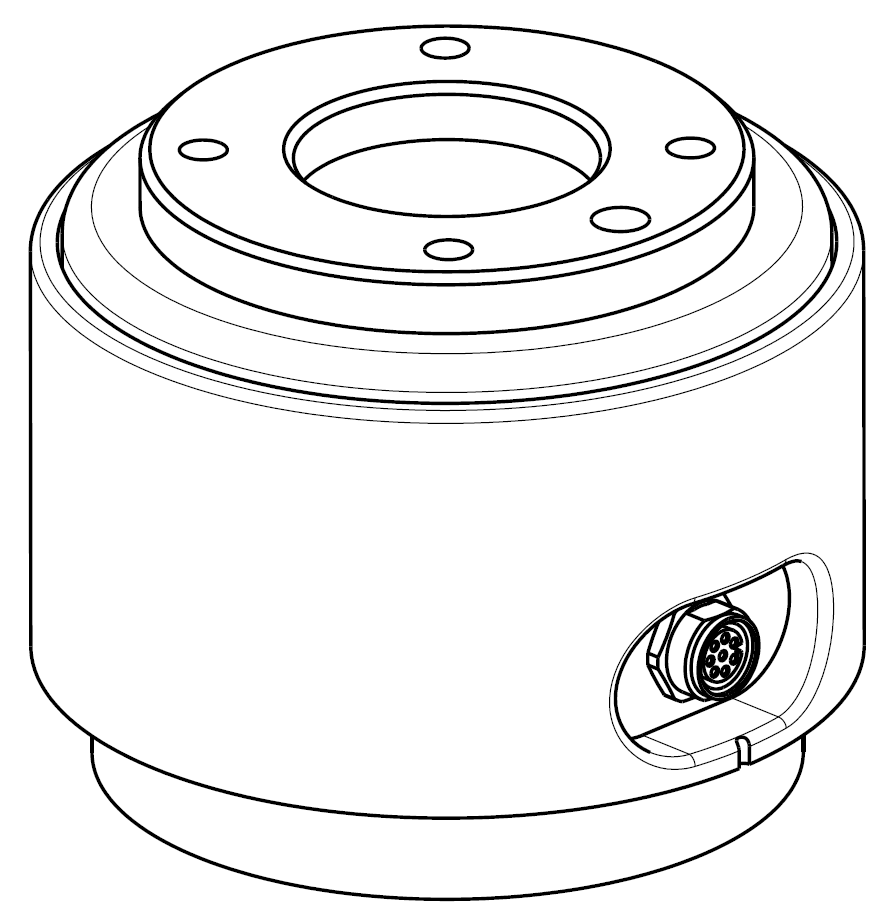
The end flange cover of the robot has one M8 spec 8-pin connector, and refer to the figure below for the location and shape.
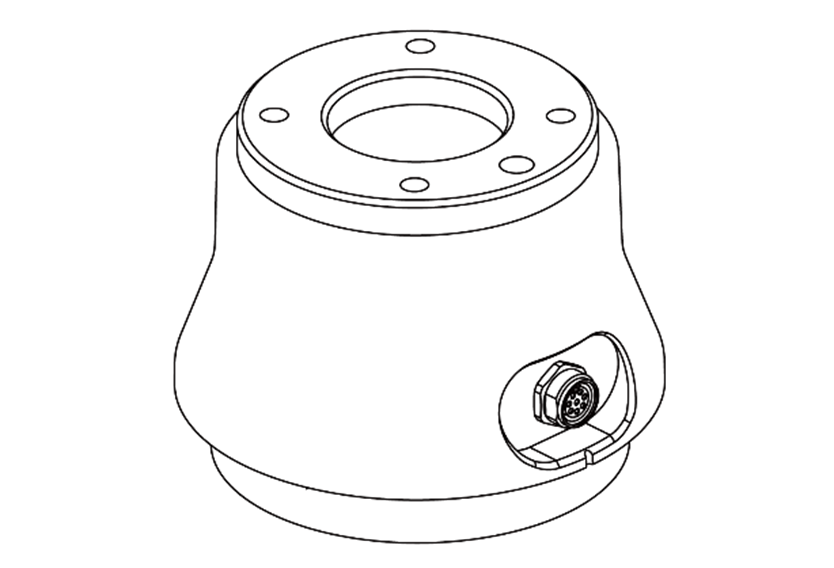
Products manufactured from August 2022 have changed their shape and connector orientation as shown in the figure below.
The connector supplies power and control signals necessary to operate the gripper or sensors embedded within specific robot tools. The following are sample industrial cables (equivalent cables can be used):
- Phoenix contact 1404178, male (Straight)
- Phoenix contact 1404182, male (Right Angle)
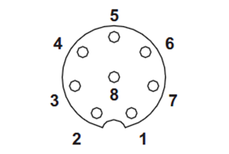
The pin map of each connector is as follows:
Schematic Diagram
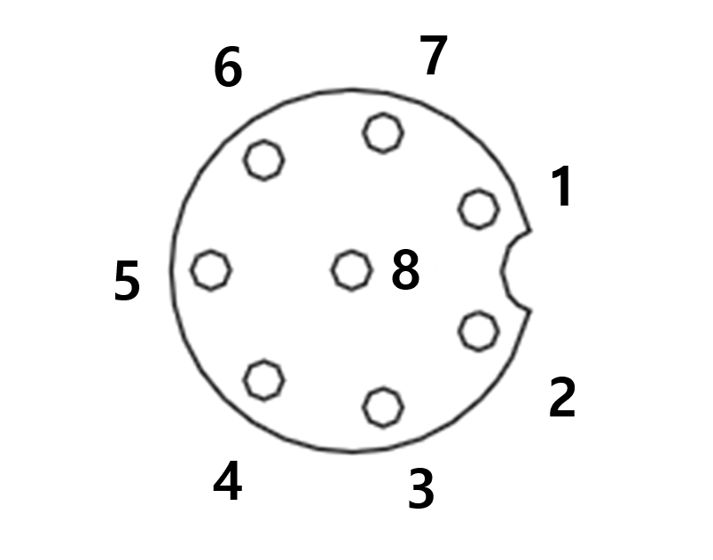
products manufactured from August 2022, the connector orientation has been changed as shown in the figure below.
The I/O functions provided through X1 connector are different from each other, and refer to the table below for detailed I/O settings.
X1 Setting (Digital I/O, RS 485)
No | Signal type | Description | Note |
1 | RS485 A | Max 1M baud rate | Mfg date 2020.07.06 ~ 2021.01.21 |
2 | RS485 B | Max 1M baud rate | |
3 | Digital Output 1 | set to either PNP (Source Type, default) or NPN (Sink Type) | |
4 | Digital Output 2 | set to either PNP (Source Type, default) or NPN (Sink Type) | |
5 | Power | +24V | |
6 | Digital Input 2 | PNP (Source Type, default) | |
7 | Digital Input 1 | PNP (Source Type, default) | |
8 | GND |
X1 Setting (Digital I/O, RS 485)
The setting has been charged as follows since January 21, 2021
No | Signal type | Description | Note |
1 | Digital Input 1 | PNP (Source Type, default) | Mfg date Before July 6, 2020 Mfg date After January 21, 2021 Other serial numbers appled VMA6F5-A0509S WAA6H7-A0912 WAA6H8-A0912 |
2 | Digital Output 1 | set to either PNP (Source Type, default) or NPN (Sink Type) | |
3 | Digital Output 2 | set to either PNP (Source Type, default) or NPN (Sink Type) | |
4 | RS485 A | Max 1M baud rate | |
5 | Power | +24V | |
6 | RS485 B | Max 1M baud rate | |
7 | Digital Input 2 | PNP (Source Type, default) | |
8 | GND |
Caution
- Configure tools and grippers after checking I/O configuration based on production date (robot label mfg date).
- You can find it on Doosan Robotlab.(https://robotlab .doosanrobotics.com)
- If you run robot tools ignoring I/O configuration, the product can be damaged permanently.
Internal power of the flange I/O is set to 24V, and refer to the table below for detailed power specifications during I/O connection.
Parameter | Min | Type | Max | Unit |
|---|---|---|---|---|
Supply voltage | - | 24 | - | V |
Supply current | - | 2 | 3 | A |
Digital output | - | 2 | - | EA |
Digital input | - | 2 | - | EA |
The setting has been charged as follows since April 11, 2024
X1 Setting
No | Signal type | Description |
|---|---|---|
1 | Digital Input 1 | PNP (Source Type, default) |
2 | Digital Output 1 | set to either PNP (Source Type, default) or NPN (Sink Type) |
3 | Digital Output 2 | set to either PNP (Source Type, default) or NPN (Sink Type) |
4 | Analog Input 1 / RS-485 + | set to either Voltage (0-10V) or Current (4-20mA, default) / Max 1M baud rate |
5 | Power | Set the internal power supply to +24V (default), +12V or 0V |
6 | Analog Input 2 / RS-485 - | set to either Voltage (0-10V) or Current (4-20mA, default) / Max 1M baud rate |
7 | Digital Input 2 | PNP (Source Type, default) |
8 | GND |
Set the internal power supply to 24V, 12V or 0V.
The electrical specifications are shown below:
| Parameter | Min | Type | Max | Unit |
|---|---|---|---|---|
| Supply voltage (12V mode) | 11.4 | 12 | 12.6 | V |
| Supply voltage (24V mode) | 22.8 | 24 | 25.2 | V |
| Supply current | - | - | 1.5 | A |
Warning
- Set up the tool and gripper so that they do not cause any hazards when power is cut off.
(e.g., workpiece falling from the tool) - The No. 5 terminal of each connector outputs 24V at all times while power is supplied to the robot, so make sure to cut the power supply to the robot when setting up the tool and gripper.