
Connecting the system
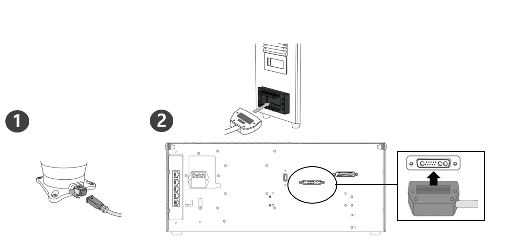
Connecting Manipulator to Controller
Description | |
|---|---|
| 1 | Connect the manipulator cable to the controller, place a securing ring
|
| 2 | Connecting the manipulator connection cable's opposite end to the controller
|
Caution
Do not disconnect the manipulator cable while the robot is turned on. This may cause the robot to malfunction.
Do not attempt any modifications or extensions to the manipulator cable.
When installing the controller on the floor, secure at least 50 mm of clearance on each side to ensure adequate ventilation.
Be sure to properly lock the connectors before turning on the controller.
Note
When configuring the system, it is recommended that a noise reducer be installed to prevent noise effects and malfunction of the system.
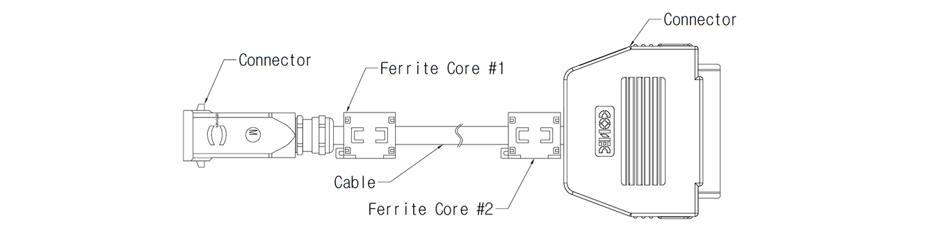
If the controller is affected by the noise generated by electromagnetic waves, it is recommended that ferrite cores be installed on both ends of the manipulator cable to ensure normal operation. The installation locations are as follows:
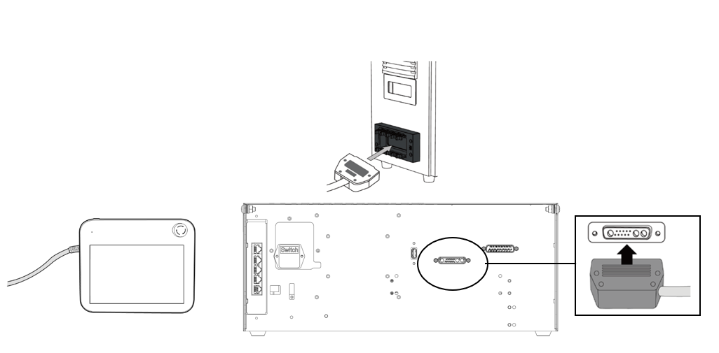
Connect Controller to Teach Pendant
Connect the teach pendant cable to the corresponding connections on the controller until it clicks and please make sure that the cable is plugged in tightly.
Caution
When connecting the cable, check the shape of the connection before connecting it so that the pin does not bend.
When using the Teach Pendant hanging on the wall or controller, be careful not to trip over the connecting cables.
Be careful not to allow the controller, Teach Pendant or cable to come in contact with water.
Avoid installing the controller or Teach Pendant in a dusty or wet environment.
The controller and Teach Pendant must not be exposed to a dusty environment that exceeds the IP20 rating. Be especially careful in environments with conductive dust.
Note
When configuring the system, it is recommended that a noise reducer be installed to prevent noise effects and malfunction of the system.
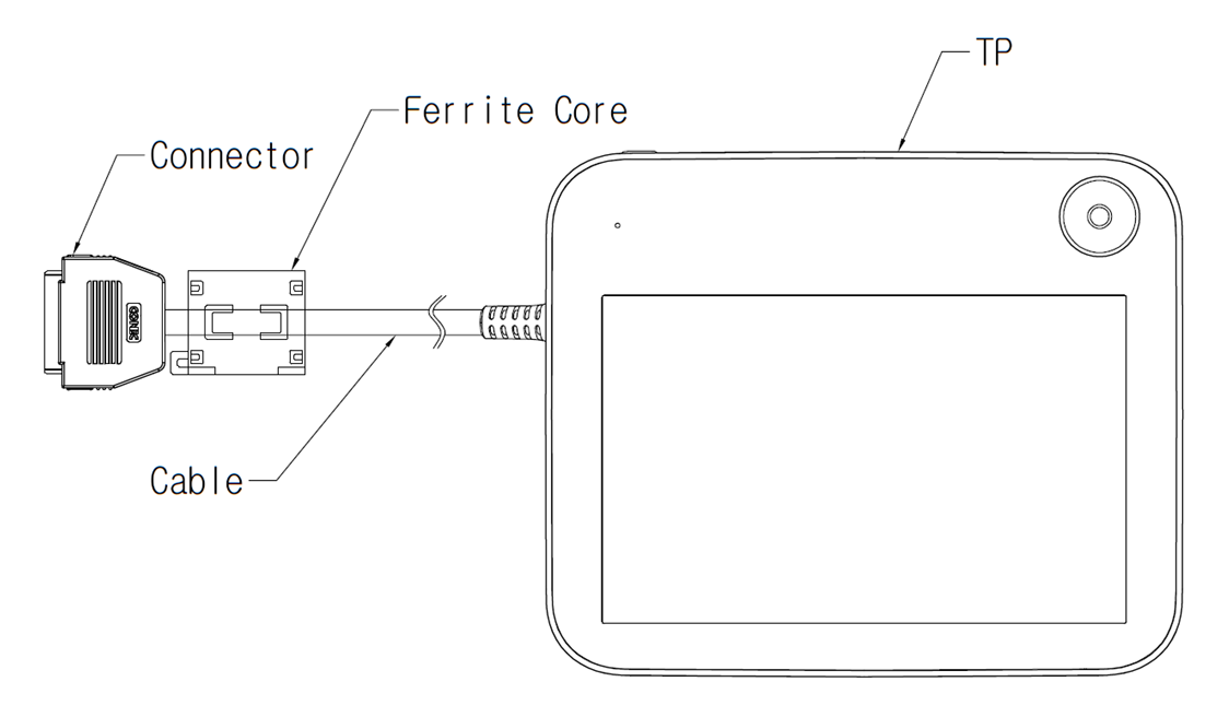
If it is affected by noise generated by electromagnetic waves, it is recommended that ferrite cores be installed on the connection parts of the Teach Pendant cable to ensure normal operation. The installation locations are as follows:
Connecting Power to Controller
To supply power to the controller, connect the power cable of the controller to a standard IEC power outlet.
When connecting, use a cable with a standard power plug that matches the outlet of country of use.
Push the plug completely into the corresponding connection of the controller to prevent the cable from becoming loose. Connect the standard IEC C14 plug under the controller to the corresponding IEC C13 cord.
Caution
Please make sure the robot is properly grounded after connecting the power cables (Electrical Ground Connections). Establish a common ground for all equipment in the system with unused bolts related to the ground symbol inside the controller. The ground conductor must satisfy the maximum current rating of the system.
Protect the input power of the controller using a circuit breaker.
Do not attempt any modifications or extensions to the power cable. It can cause fire or controller breakdown.
Make sure that all cables are properly connected before supplying power to the controller. Always use the original cable included in the product package.
Note
When configuring the system, it is recommended to install a power switch capable of turning all devices off at once.
The power supply must satisfy minimum requirements such as ground and circuit breakers. The electrical specifications are as follows: (For optional controllers, refer to their respective appendix.)
Parameter | Specifications |
|---|---|
Input Voltage | 100 – 240 VAC |
Input Power Fuse (@100-240V) | 15 A |
Input Frequency | 47 – 63 Hz |