
Flange I/O
The end flange cover of the robot has one M8 spec 8-pin connector, and refer to the figure below for the location and shape.
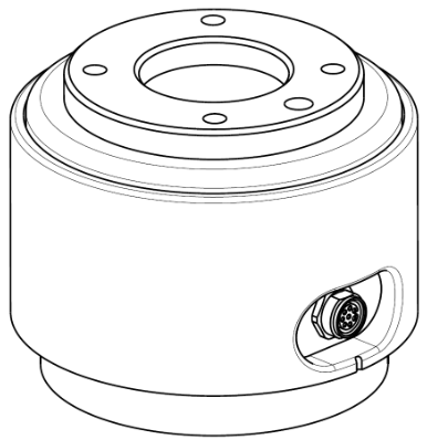
The connector supplies power and control signals necessary to operate the gripper or sensors embedded within specific robot tools. The following are sample industrial cables (equivalent cables can be used):
Phoenix contact 1404178, male (Straight)
Phoenix contact 1404182, male (Right Angle)
Schematic Diagram
The pin map of each connector is as follows:
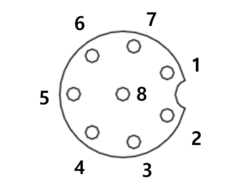
Please refer to the table below for detailed I/O configuration provided by the X1 connector.
X1 Setting
No | Signal type | Description |
|---|---|---|
1 | Digital Input 1 | PNP (Source Type, default) |
2 | Digital Output 1 | set to either PNP (Source Type, default) or NPN (Sink Type) |
3 | Digital Output 2 | set to either PNP (Source Type, default) or NPN (Sink Type) |
4 | Analog Input 1 / RS-485 + | set to either Voltage (0-10V) or Current (4-20mA, default) / Max 1M baud rate |
5 | Power | Set the internal power supply to +24V (default), +12V or 0V |
6 | Analog Input 2 / RS-485 - | set to either Voltage (0-10V) or Current (4-20mA, default) / Max 1M baud rate |
7 | Digital Input 2 | PNP (Source Type, default) |
8 | GND |
The flange input/output (I/O) initial power is set to 24V and can be set to 0V or 12V.
Refer to the table below for detailed power specifications during I/O connection.
Parameter | Min | Type | Max | Unit |
|---|---|---|---|---|
Supply voltage (12V mode) | 11.4 | 12 | 12.6 | V |
Supply voltage (24V mode) | 22.8 | 24 | 25.2 | V |
Supply current | - | - | 1.5 | A |
Warning
Set up the tool and gripper so that they do not cause any hazards when pt cause any hazards when power is cut off.
(e.g., workpiece falling from the tool)The No. 5 terminal of each connector outputs 24V at all times while power is supplied to the robot, so make sure to cut the power supply to the robot when setting up the tool and gripper.
Flange Digital Output Specifications
Flange digital output is a PNP specification, and photo coupler output is set up in the output.
The corresponding output channel becomes +24V when digital output is activated. When digital output is disabled, the state of the corresponding output channel is open (floating).
The electrical specifications of the digital output are as follows:
Parameter | Min | Type | Max | Unit |
|---|---|---|---|---|
Voltage when driving 10mA | 23 | - | - | V |
Voltage when driving 50mA | 22.8 | - | 23.7 | V |
Current when driving | 0 | - | 50 | mA |
The setting has been changed as follows since April 11, 2024
Digital Ou Outputs support two differefferent modes:
Mode | Active | Inactive |
|---|---|---|
PNP (Source Type, default) | High | Open |
NPN (Sink Type) | Low | Open |
The flange input/output (I/O) initial power is set to 24V and can be set to 0V or 12V.
The corresponding output channel becomes ++12V or ++24V when digital output is activated.
When digital output is disabled, the state of the corresponding output channel is open (floating).
The electrical specifications of the digital output are as follows:
Parameter | Min | Type | Max | Unit |
|---|---|---|---|---|
Voltage when driving 12V mode | 11.4 | 12 | 12.6 | V |
Voltage when driving 24V mode | 22.8 | 24 | 25.2 | V |
Current when driving | 0 | - | 50 | mA |
Caution
Digital output is not subject to current limitation. Ignoring the specifications presented above during operation may cause permanent damage to the product.
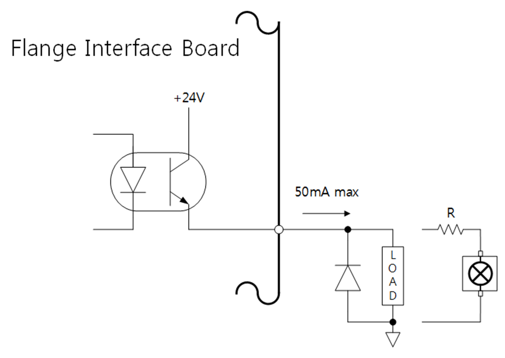
The figure below is an example of a digital output setup, so refer to it while connecting the tool and gripper.
Make sure to disconnect the power from the robot when setting up the circuit.
Flange Digital Input Specifications
Flange digital input features a photo coupler input.
The current based on 24V input is limited to 5mA by internal resistance.
The electrical specifications of the digital input are as follows:
Parameter | Min | Type | Max | Unit |
|---|---|---|---|---|
Input voltage | 0 | - | 26 | V |
Logical high | 4.4 | - | - | V |
Logical low | 0 | - | 0.7 | V |
Input resistance | - | 4.4k | - | Ω |
Caution
The figure below is an example of a digital input setup, so refer to it while connecting an input device.
Make sure to disconnect the power from the robot when setting up the circuit.

Flange Analog Input Specifications
Receives voltage or current signals from external devices.
Analog Input can be set to voltage (0-10V) or current (4-20mA).
The electrical specifications are shown below.
Parameter | Min | Type | Max | Unit |
|---|---|---|---|---|
Input voltage in voltage mode | 0 | - | 10 | V |
Input current in current mode | 4 | - | 20 | mA |
Resolution | - | 12 | - | bit |