
Robot system configuration and description
Component List
 |  |
Manipulator | Controller (optional(optional: see Appendix) |
 | 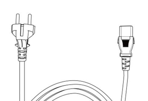 |
Teach pendant | Controller power cable |
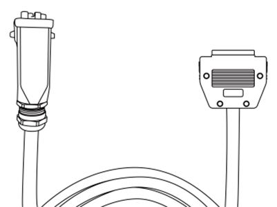 |  |
Manipulator connection cable | User manual / quick guide |
Name of each part and Functions
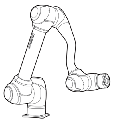
Manipulator
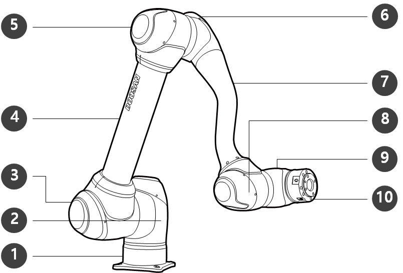
Name of each part
No. | Name | No. | Name |
|---|---|---|---|
1 | Base | 6 | J4 |
2 | J1 | 7 | Link2 |
3 | J2 | 8 | J5 |
4 | Link1 | 9 | J6 |
5 | J3 | 10 | Tool Flange |
ㅤ
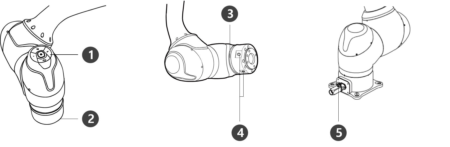
Key Features
No. | Items | Description |
|---|---|---|
1 | Cockpit | [Optional] Operation buttons for direct teaching and operation |
2 | Tool Flange | Area to install tools. |
3 | 3 | Displays the robot status with different colors. For more information about robot status, refer to the Status and Flange LED Color for Each Mode. Version: H Series The The H Series is supplied with an additional LED on the 1-axis indicating the same state and color. |
4 | Flange I/O | I/O port for tool control. |
5 | Connector | Used for supplying power to and communication of the robot. |
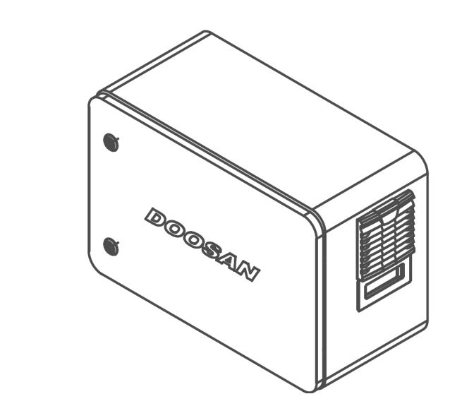
Controller
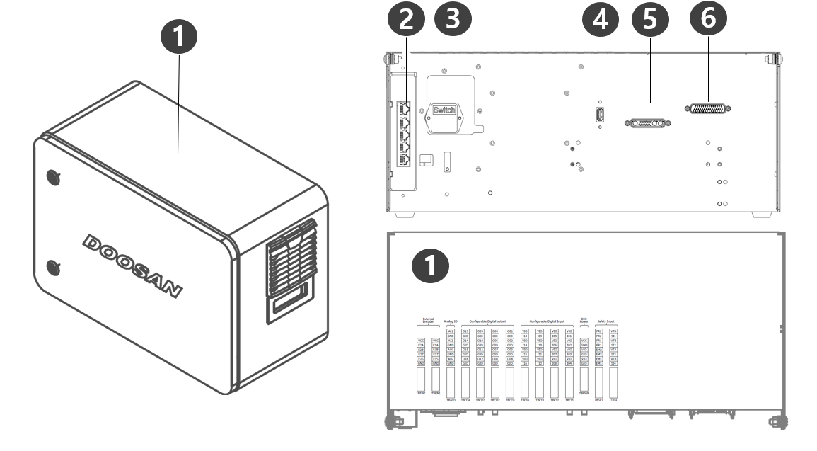
No. | Items | Description |
|---|---|---|
1 | I/O connection terminal (internal) | It can be connected with other robots' controllers or peripherals. |
2 | Network connection terminal | Used for connecting to the network connection terminal inside the controller to use Laptops, TCP/IP devices, and and Modbus equipment. |
3 | Power connection terminal/switch | Used for connecting the mains power of the controller to turn it on or off. For more information, refer to Power on/off the system. |
4 | USB connection terminal | Used to store logs created while the robot is operating in the USB storage, or export and import tasks. |
5 | Manipulator cable connection terminal | Used for connecting the manipulator cable to the controller. |
6 | Teach pendant cable connection terminal | Used for connecting the teach pendant cable to the controller. |
Note
If you choose an optional controller, check the user manual in the appendix to connect before use.
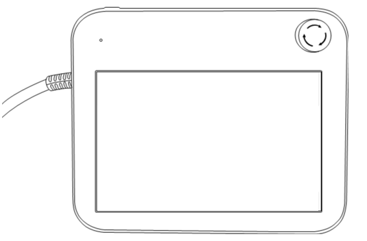
Teach pendant

No. | Items | Description |
|---|---|---|
1 | Power Button |
|
2 | Power LED |
|
3 | Emergency stop button |
|
4 | Hand-Guiding button (3PE 3 Position Enable Switch) |
|
Note
If the teach pendant needs to be protected and mounted during operation, the soft cover supplied by us makes it safer and easier to use.
New TP (TP-02) added function: Hand Guide dual function
The existing TP (TP-01) cannot be used in the integrated controller. (Pin Map changed due to 3PE Switch)
The new TP (TP-02) can be used in the existing controller, but the LED is changed to a single color (red) and displayed, and additional functions cannot be used.
System Configuration
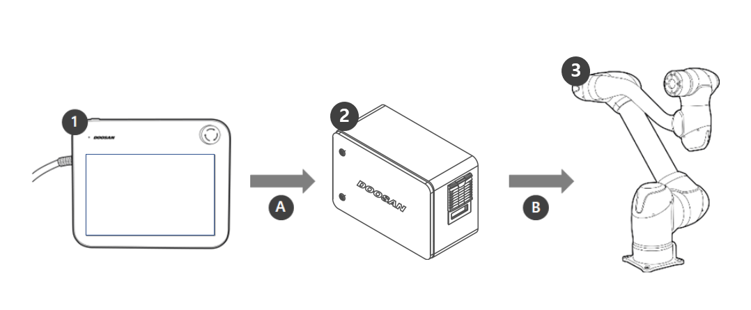
No. | Name | Description |
|---|---|---|
1 | Teach pendant | This device manages the entire system and is capable of teaching the robot specific poses or making settings related to the manipulators and controllers. |
2 | Controller | It controls the robot’s movement according to the pose or movement set by the teach pendant. It features various I/O ports that allow the connection and use of various equipment and devices. |
3 | Manipulator | It is an industrial collaborative robot that can perform transport or assembly tasks with various tools. |
A | Command/Monitoring | |
B | Power Supply/Network |