
DC Controller (CS-12P)
Product Introduction (CS-12P)
Name of each part and Functions
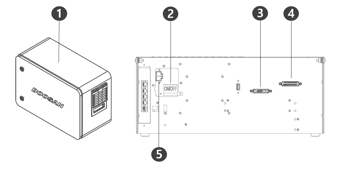
No. | Items | Description |
1 | I/O connection terminal (internal) | It can be connected with other robots' controllers or peripherals. |
2 | Power switch | Used to turn ON/OFF the main power of the controller . |
3 | Teach pendant cable connection terminal | Used for connecting the teach pendant cable to the controller. |
4 | robot cable connection terminal | Used to connect the robot cable to the controller. |
5 | Power connection terminal | Used to connect the controller power supply. |
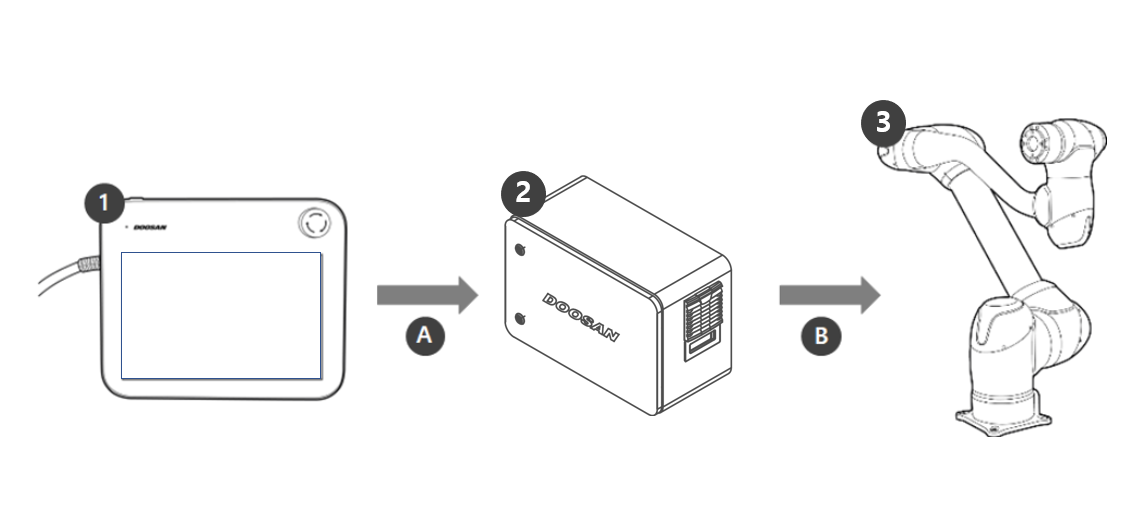
System Configuration
No. | Name | Description |
|---|---|---|
1 | Teach pendant | This device manages the entire system and is capable of teaching the robot specific poses or making settings related to the manipulators and controllers. |
2 | Controller | It controls the robot’s movement according to the pose or movement set by the teach pendant. It features various I/O ports that allow the connection and use of various equipment and devices. |
3 | Manipulator | It is an industrial collaborative robot that can perform transport or assembly tasks with various tools. |
A | Command/Monitoring | |
B | Power Supply/Network |
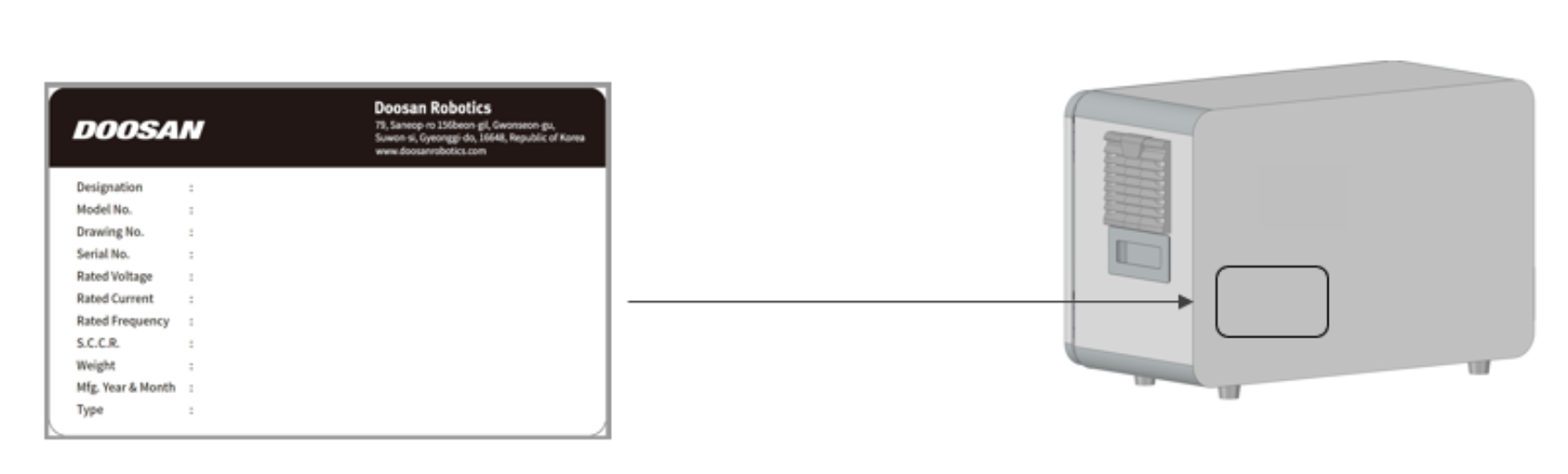
Nameplate and Label
Installation (CS-12P)
Cautions during Installation
Caution
Secure sufficient space before installing the controller. If not enough space is secured, the controller may be damaged or the manipulator or teach pendant cable may have a shortage.
Check the input power supply when connecting power to the product. If the connected input power supply is different from the rated power input (22-60VDC), the product many not operate properly or the controller may be damaged.
Installation Environment
When installing the controller, consider the following.
Secure sufficient space before installing the controller.
The controller must be fixed.
Make sure no component is not fixed in the mobile vehicle.
Hardware Installation
Install the robot, controller and teach pendant, the key components of the system, and supply power to them before operating the manipulator. The instruction for installing each element is as follows:
Connecting Manipulator to Controller
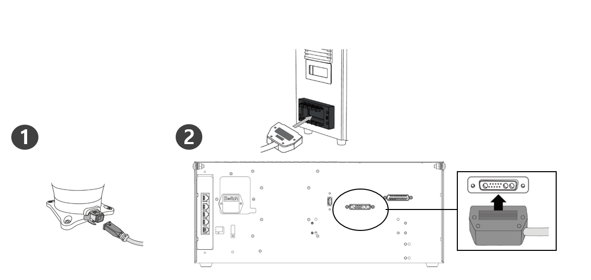
Description | |
|---|---|
1 | Connect the manipulator cable to the controller, place a securing ring
|
2 | Connecting the manipulator connection cable's opposite end to the controller
|
Caution
Do not disconnect the manipulator cable while the robot is turned on. This may cause the robot to malfunction.
Do not attempt any modifications or extensions to the manipulator cable.
When installing the controller on the floor, secure at least 50 mm of clearance on each side to ensure adequate ventilation.
Be sure to properly lock the connectors before turning on the controller.
Note
When configuring the system, it is recommended that a noise reducer be installed to prevent noise effects and malfunction of the system.
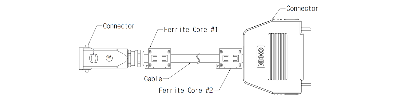
If the controller is influenced by noise generated by electromagnetic waves, it is necessary to install a ferrite core to ensure normal operation. The installation location is as follows:
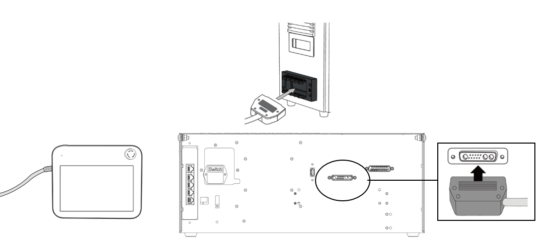
Connect Controller to Teach Pendant
Connect the teach pendant cable to the corresponding connections on the controller until it clicks and please make sure that the cable is plugged in tightly.
Caution
When connecting the cable, check the shape of the connection before connecting it so that the pin does not bend.
If the teach pendant is used by hanging on the mobile vehicle or on the controller, be careful not to trip on the connecting cables.
Be careful not to allow the controller, teach Pendant and cable to come in contact with water.
Do not install the controller and teach pendant in a dusty or wet environment.
Controllers and smart pendant must never be exposed to dust environment above IP20 grade. Be especially careful in environments with conductive dust.
Note
When configuring the system, it is recommended that a noise reducer be installed to prevent noise effects and malfunction of the system.
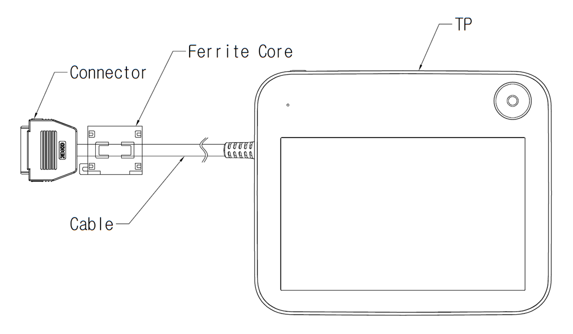
If the teach pendant is influenced by noise generated by electromagnetic waves, it is necessary to install a ferrite core to ensure normal operation. The installation location is as follows:
Placing Manipulator Cable and Teach Pendant Cable
Ensure that the manipulator and teach pendant cable curvature radius is greater than the minimum curvature radius (120 mm).

Caution
Ensure that the curvature radius between the teach pendant cable and teach pendant connector is greater than the minimum curvature radius (120 mm).
If the curvature radius is smaller than the minimum curvature radius (120 mm), cable disconnection or product damage may occur.
In environments where electromagnetic noise can occur, proper cable installation must be taken to prevent malfunctions.
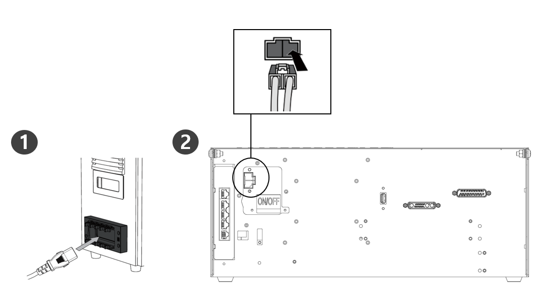
Connecting Power to Controller
Connect the power cable to the corresponding connections on the controller until it clicks and please make sure that the cable is plugged in tightly.
Warning
Please make sure the robot is properly grounded after connecting the power cables (Electrical Ground Connections). Establish a common ground for all equipment in the system with unused bolts related to the ground symbol inside the controller. The ground conductor must satisfy the maximum current rating of the system.
Protect the input power of the controller using devices such as a circuit breaker.
Do not modify or extend the robot cable. It can cause fire or controller breakdown.
Make sure that all cables are properly connected before supplying power to the controller. Always use the original cable included in the product package.
Be careful not to connect the polarity of the input voltage incorrectly.
Note
When configuring the system, it is recommended to install a power switch capable of turning all devices off at once.
When using a controller for DC, the robot's motion may be limited depending on the load and motion.
If the input voltage is less than 48V, the robot’s movement may be limited according to the load and motion.
The power supply must satisfy minimum requirements such as ground and circuit breakers. The electrical specifications are as follows:
Parameter | Specifications |
Input Voltage | 22 – 60 VDC |
Rated input current | 30 A |