
Jog Screen
Jog Menu Layout
| Item | Description | |
|---|---|---|
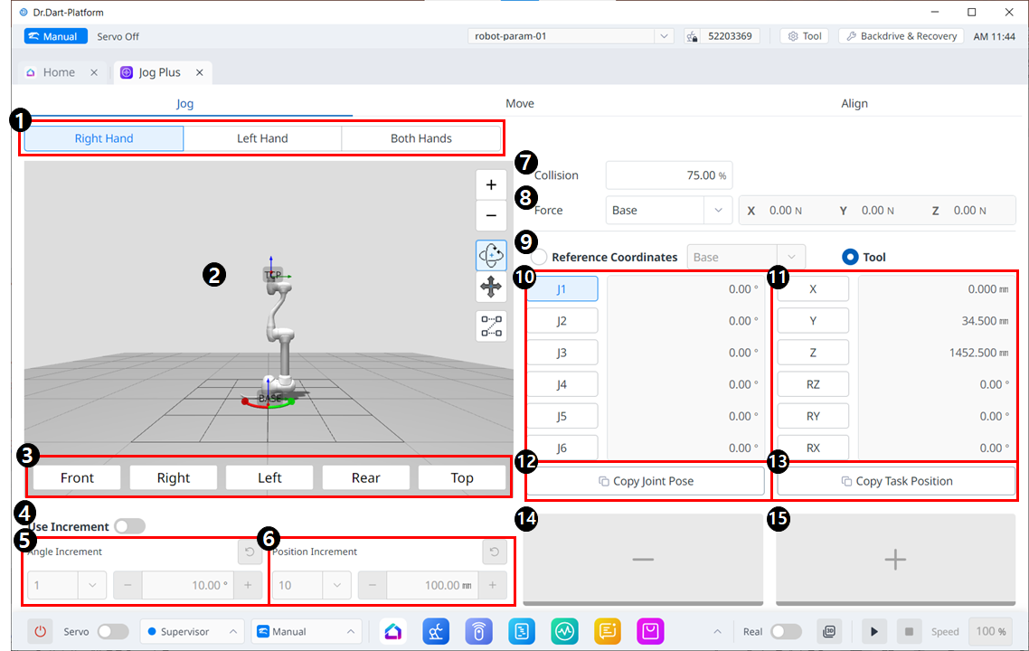
| 1 | Select panel type | You can choose the location of the move button. |
| 2 | 3D simulation | This is the 3D viewer, where you can see how the robot looks. |
| 3 | Simulator Alignment | You can utilize this section to steer the simulator. |
4 | Use Increment | This button allows you to enable angle or position increments. |
| 5 | Angle Increment | This section is where the angle increment on the selected axis is set. |
| 6 | Position Increment | This section is where the position increment on the selected axis is set. |
| 7 | Collision | This field is where you set the Robot Collision. |
| 8 | Force Monitoring | This section is where you set the forces in the X, Y, and Z axes based on Base, Tool, World, Reference and among others. |
| 9 | Select reference coordinate system | Select a reference coordinate system to display or jog the task coordinates in Figure 11. It can be Base, World, or User coordinates. |
| 10 | Joint panel | You can select the joint axis to jog. |
| 11 | Task panel | You can select the task axis to jog. |
| 12 | Copy Pose J button | This button allows you to copy Pose J. |
| 13 | Copy Pose X button | This button allows you to copy Pose X. |
| 14 | Move - Button | You can have the robot move in the - direction based on each axis. At this time, you can figure out the direction of the - and + on the 3D simulation on the left-hand side. |
| 15 | Move + Button | You can have the robot move in the + direction based on each axis. At this time, you can figure out the direction of the - and + on the 3D simulation on the left-hand side. |