
Coordinate Settings
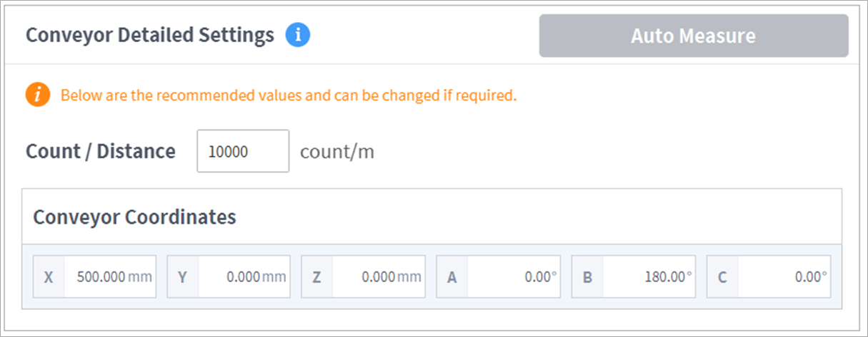
The purpose of the Coordinates tab is to set the Count/Distance values and the conveyor coordinates under Conveyor Detailed Settings. This calculates the converted value, which indicates how much the encoder count increases when the conveyor moves, and which point the conveyor is fixed to in a particular space.
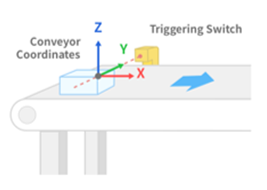
The x-axis of the conveyor coordinates is the direction of the conveyor’s movement in terms of the reference coordinates (Base or World).
Methods to calculate these values are Auto Measure, after teaching the conveyor teaching points to the robot, and Manual Calculation from the system design specifications. It is possible to use Manual Calculation if it is difficult to teach the robot about the workpiece, but Auto Measure is recommended in most scenarios.
Auto Measure
Teaching consists of placing the workpiece before the workpiece detection switch, operating the conveyor, and stopping the conveyor intermittently to teach the robot to obtain position information. Check that the TCP is identically set in the program to be used before teaching.
Base Coordinates and World Coordinates can be selected as the reference coordinates during teaching. World Coordinates is helpful as it allows two robots to share a single conveyor without re-teaching.

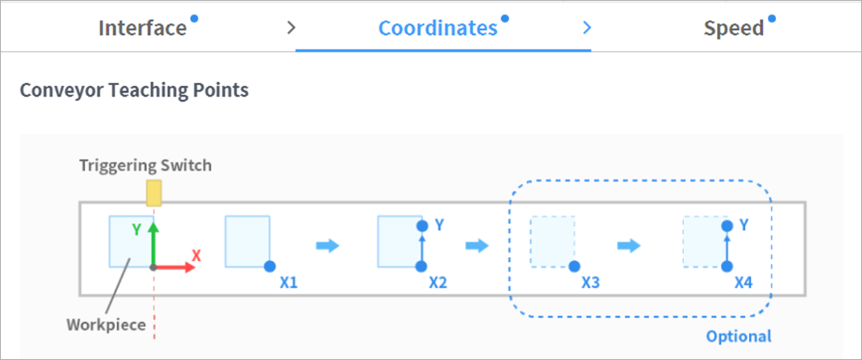
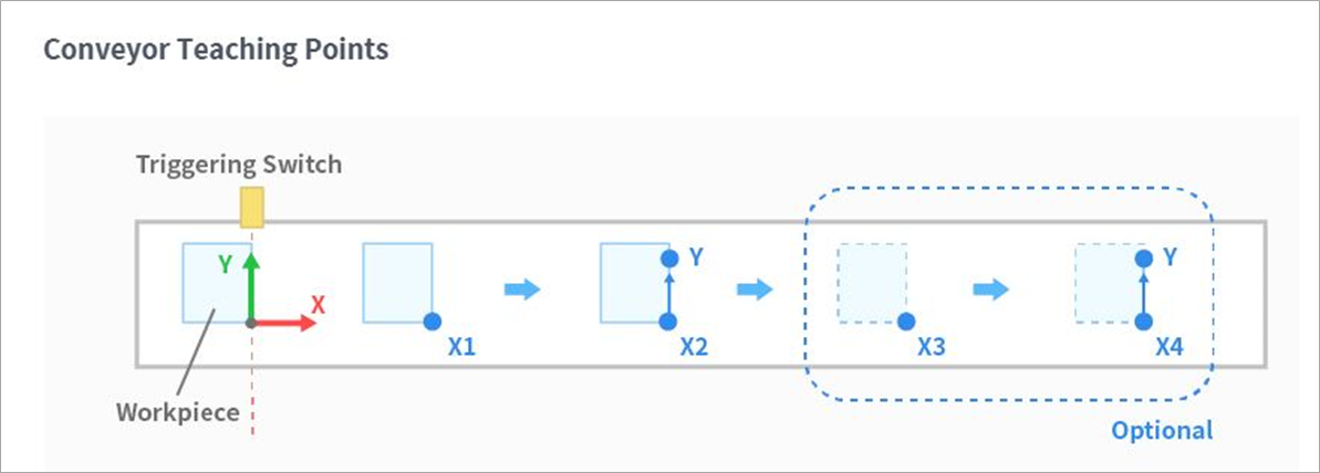
Place a workpiece on the conveyor before the workpiece detection switch in the same way it is done during actual work. Turn on the conveyor and stop it after the workpiece passes the conveyor’s triggering switch. Teach the reference point of the workpiece at this moment, and press Save Pose to acquire the current encoder count and robot location of Point X1.
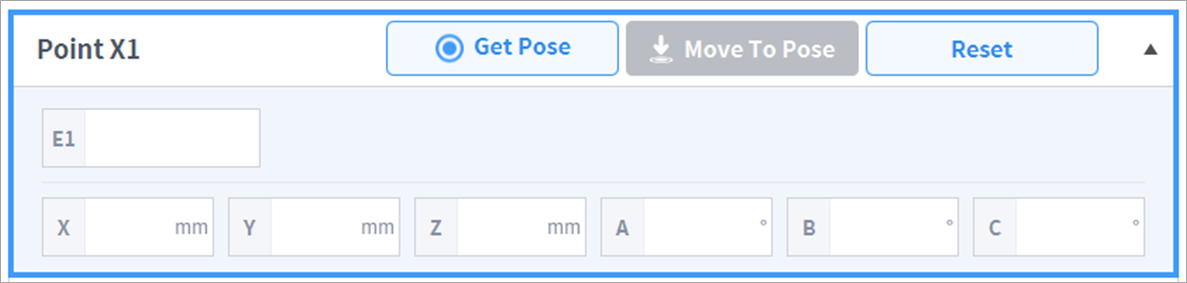
Turn on the conveyor again and stop it in the same way to acquire a location for Point X2. Point X is used to calculate the x-axis of the conveyor coordinates. While just X1 and X2 are sufficient, up to four points can undergo teaching to improve accuracy. Depending on the number of teachings, spread the position within the range where the robot can undergo teaching.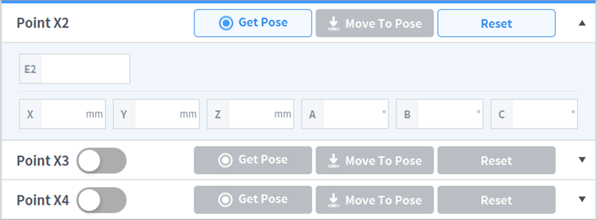
Point Y is used to calculate the y-axis of the conveyor coordinates, so it is acquired by teaching a workpiece placed on an X-Y plane to generate a y-axis in addition to Point X.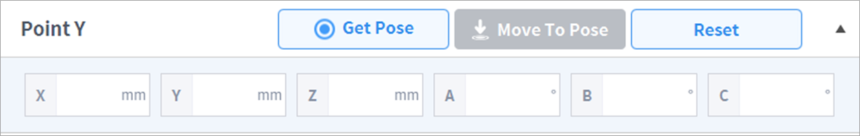
Acquire a teaching point and press Auto Measure to automatically calculate Conveyor Detailed Settings. Check whether the conveyor coordinates are calculated to a point near the physical location of the triggering switch. (Depending on the detected edge, offset may exist in the direction of the conveyor)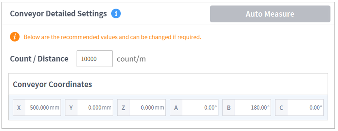
Manual Setting
The workpiece’s location is calculated by applying the encoder count, increasing in the direction of x for the conveyor coordinates, when the workpiece passes the triggering switch. The setting is set based on the triggering switch, conveyor position and workpiece reference point, and even in situations where it is difficult to identify the exact position, setting the correct x-axis direction for Conveyor Coordinates will allow the remaining offset to be accurately entered in Task Motion under TB/TW, so it is acceptable to not enter the exact value.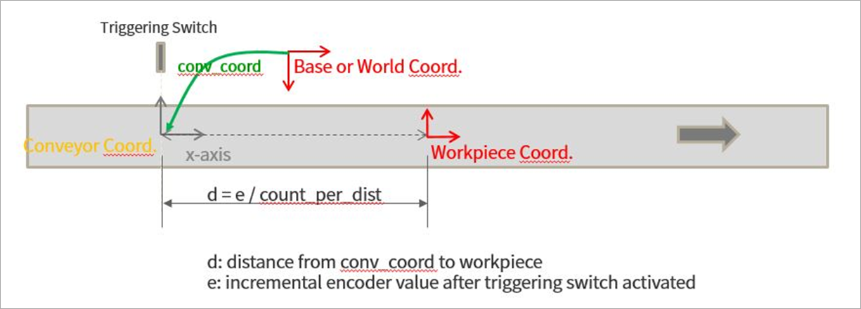
Count and Distance are conveyor tracking commands in TB/TW, and entering the Wait command without a task motion will result in the tracking of conveyor movement from the current position. The user can adjust this while monitoring the speed trend. If the robot moves more slowly than the conveyor, reduce the Count/Distance, and if the robot moves faster, increase the Count/Distance.