Camera Calibration
Camera - Robot Calibration is the process of synchronizing the coordinate information measured by the camera with the coordinate information of the robot.
With Calibration, the camera can accurately move to the location of the measured item, and it can accurately measure dimensions in terms of length. During Calibration, a checkerboard with predefined design information is used. The method currently offered by Doosan Robotics is StandAlone calibration, and the elements required for this calibration are four robot poses taught based on the camera image of the checkerboard shot from the shooting position and tool tip.
Caution
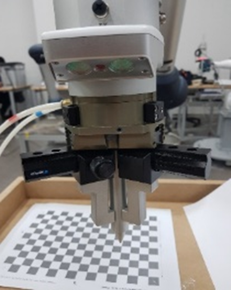
During calibration, it is necessary to align the camera lens and the checkerboard in parallel as much as possible. In addition, when performing calibration, the calibration board must be placed at the surface height of the item to be measured. If the height of the checkerboard during calibration differs from the surface height of the item to be measured, it can cause failure to detect the item or decrease measurement accuracy.
Additional Functions available with the SVM
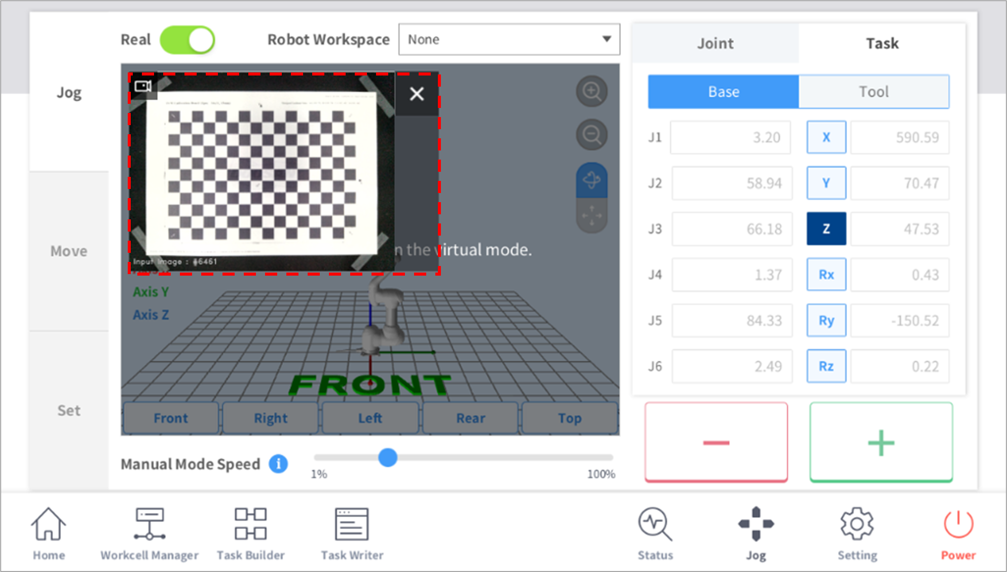
- The Live screen is displayed on the Jog
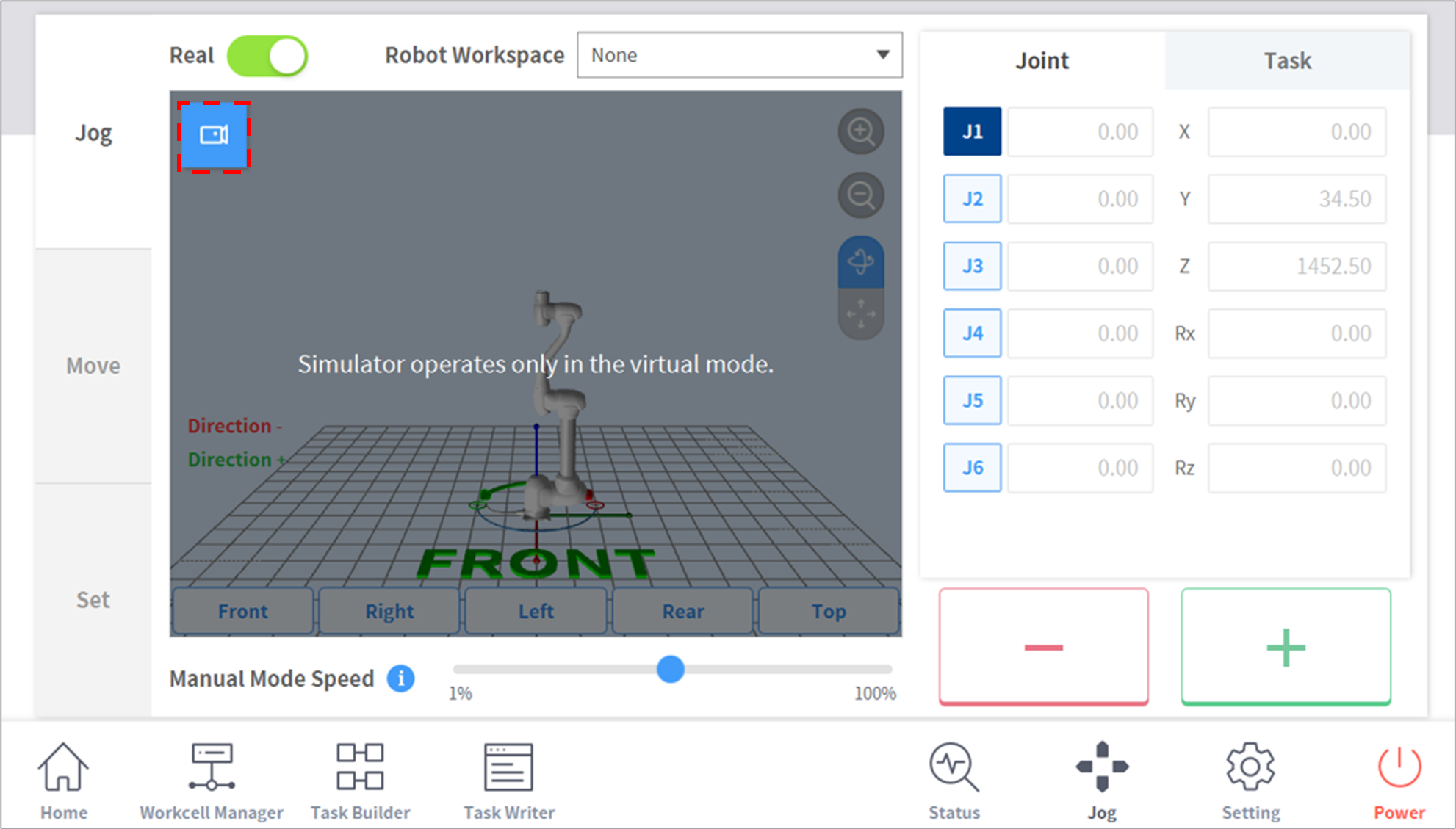
If the Vision license is entered, a live image can be viewed in the Jog tab. The user can operate the robot while viewing the live image.
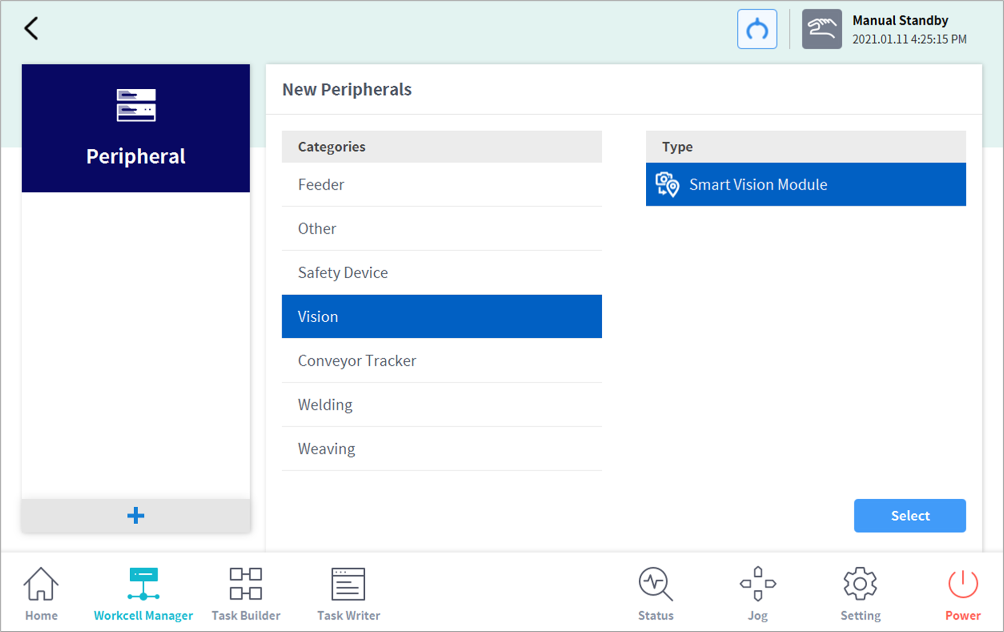
- Added Vision category to Peripheral
SVM Calibration Board Download
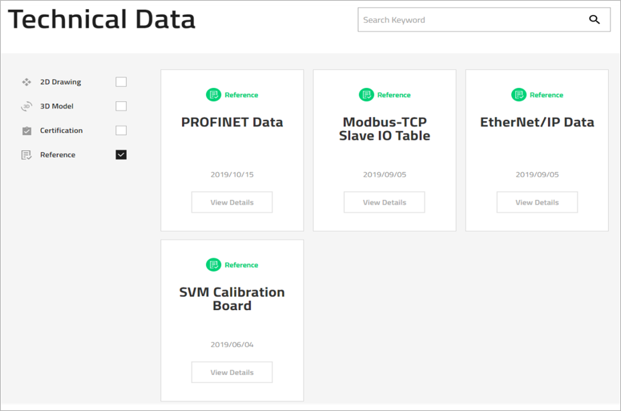
- The SVM Calibration Board can be downloaded from [https://lab.doosanrobotics.com/en/Index Robot LAB – Resources – Tech Data – Reference] after logging in.
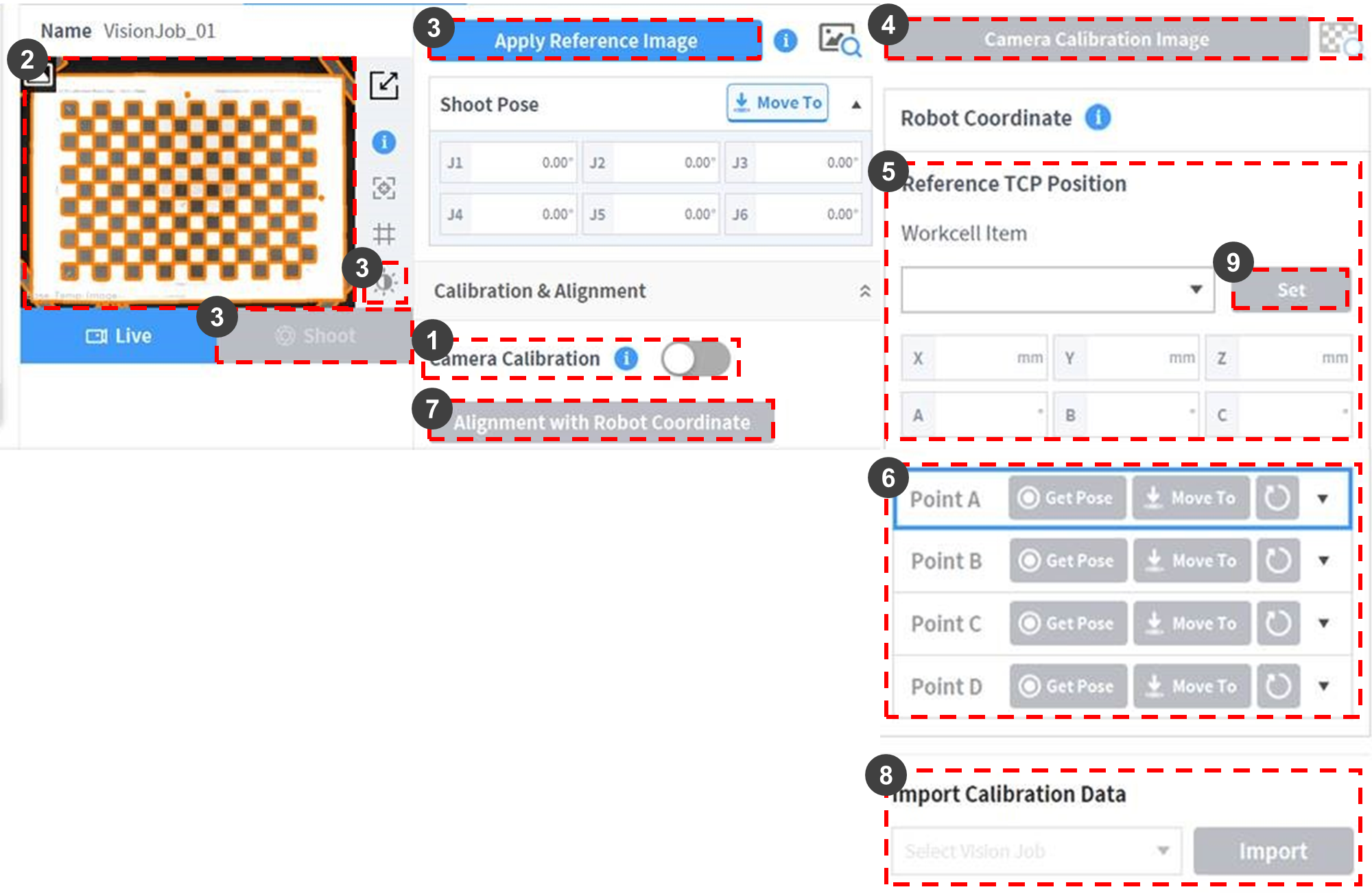
No. | Item | Description |
1 | Camera Calibration | Enables Camera - Robot Calibration function.
|
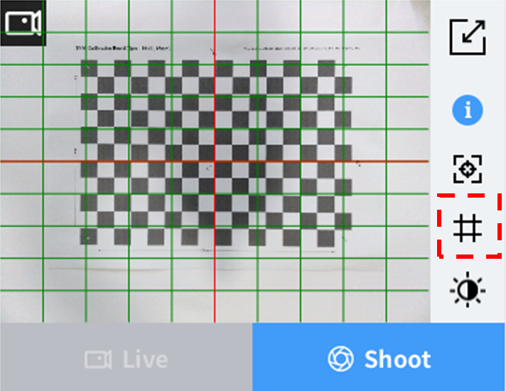
2 | Live/Shoot Image | The Live/Shoot Image can be checked. To ensure proper camera calibration, a checkerboard is placed as follows:
|
3 | Lighting Setting/ | Adjust the focus, brightness and lighting to display the edge of the checkerboard clearly.
|
4 | Camera Calibration Image | Run checkerboard corner point detection.
Note
|
5 | Load TCP Setting | Sets the information of the Tool currently equipped on the robot as TCP.
|
6 | Obtain PointA - PointD Points | Obtains the robot pose [x, y, z, rx, ry, rz] of PointA - PointD.
|
7 | Alignment with Robot Coordinate | Run the camera - robot coordinate matching calculation. After calculation is completed, the results are displayed. If successful,save the Calibration information in the camera. To save the Calibration information in the UI, press the Confirm button on the top of the Workcell Manager. Success ( Success Criteria • All grid patterns of the checkerboard must be displayed on the image. • Dark grid patterns of the checkerboard must be positioned on the top/bottom left. • Check whether all corner points are detected using View Image. • TCP information identical to the information of the tool equipped must be set. • Enter corner points of ABCD of the checkerboard with direct teaching to the robot. • Teach the robot tool the exact positions of ABCD corner points of the checkerboard. • The checkerboard position must not change during direct teaching. Failure Criteria • If all corner points of the checkerboard are not detected. • If the direct teaching order of ABCD corner points of the checkerboard is incorrect. • If the set TCP information does not match the information of the Tool equipped. • If the direct teaching of corner points of the checkerboard is not accurate. • If the ABCD coordinates measured by the camera are different from the ABCD coordinates taught to the robot by direct teaching (calibration fails if a deviation of more than 5 mm occurs). Items to Check Upon Failure • Check the position/direction of the checkerboard. • Check whether edges of the checkerboard are clearly displayed. • Check whether direct teaching was performed in the order of ABCD. • Check whether the TCP setting is correct. • Check whether the checkerboard print was moved after Camera Calibration Image. • Check whether the ABCD corner points of the checkerboard were taught accurately. |
8 | Import Calibration Data | Imports calibration data that succeeded in existing vision works. • Select a vision work to import the calibration data and press the import button to save the corresponding calibration data. |
9 | Set | Sets the Workcell Item loaded on the left of the Set button to the current tool center point. |