
Tool
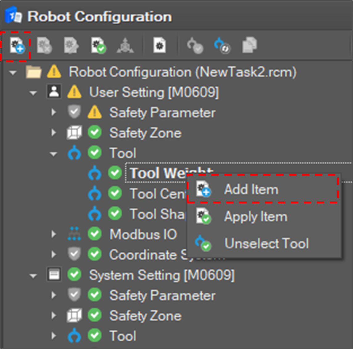
Add an item to set a tool
To register a tool setting, select Tool Weight, Tool Center or Tool Shape and click the Add Item
- It is also possible to add an item by selecting Add Item on the context menu.
Edit a tool setting
Fill the tool properties.
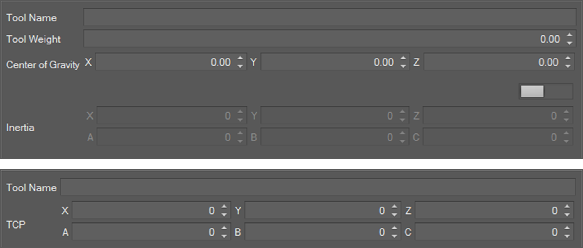
You can automatically measure the tool weight by clicking the Measure button.
If measurement is done, the measure result is filled in the tool weight fields.
You can automatically calculate the TCP by clicking the Calculate button. If you click it, the TCP Calculating window opens. After filling in the four reference values required for TCP calculation, press the measure button to start the measurement motion. During motion, the measure button changes to a stop button, and the measurement motion stops when the stop button is pressed.
If calculation is done, the result is filled in TCP fields.
If editing is done, click the Confirm button.
Then, the setting is registered in the system.
Activate a tool
To activate a tool, select a tool item and click the Apply Item 
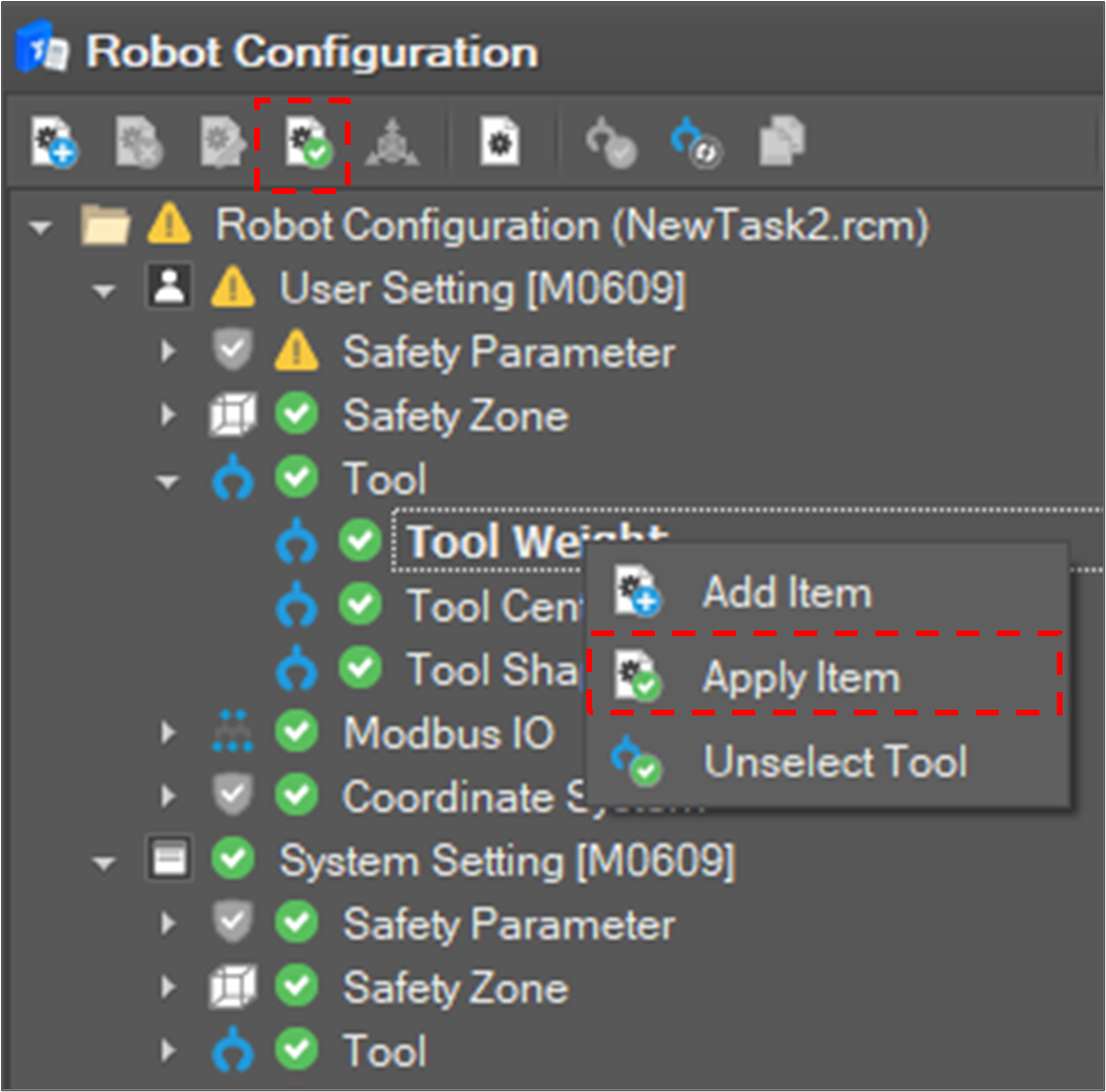
Then, the selected tool is set as an active tool.
Unselect a tool
Click the Unselect Tool 
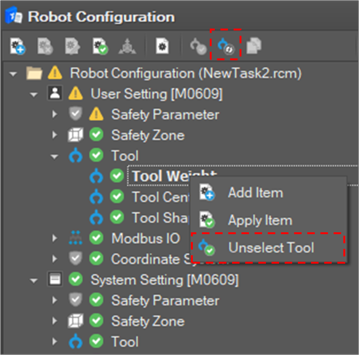
Then, the active tool is reset.
Modify a tool shape Item
To set tool shape setting, select an added item and click the Modify Item 
- It is also possible to modify it by selecting Modify Item on the context menu.
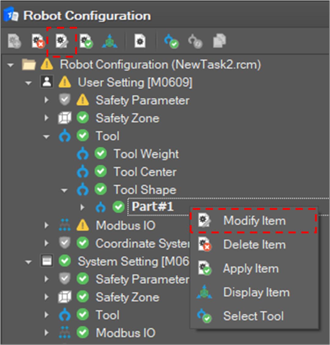
Then, the edit window appears on the right side.
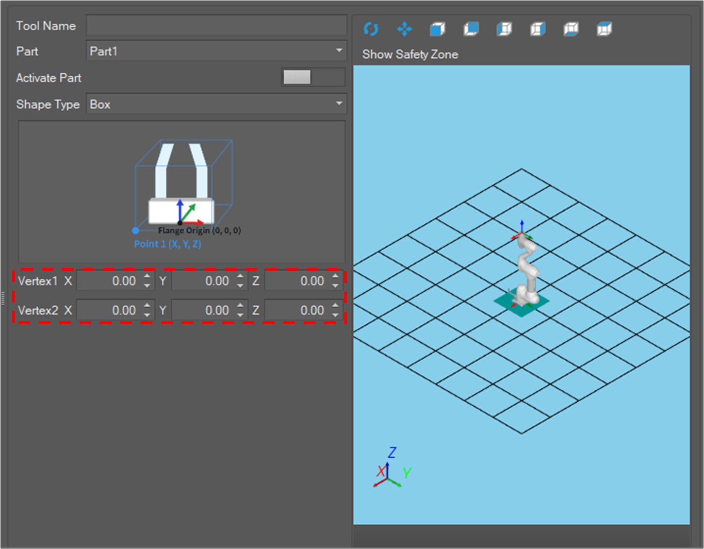
Tool shape is composed of at most five parts, and each part’s shape is one of Box, Sphere or Capsule. To configure the shape of a part, you must set its validity flag and shape.
- Select the part in the Tool Shape list.
- Click the Modify Item button on the toolbar or select Modify Item on the context menu.
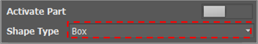
- Select Shape Type.
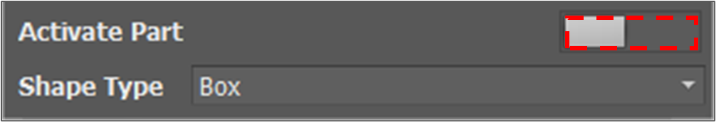
- Turn on the Activate Part button if you want to enable a part.
- Define shape
- It is assumed that the origin of the tool shape is in the “Tool Flange Center” and its X, Y, Z direction is the same as the Base coordinate system X, Y, Z direction.
- If every field is filled and the shape is valid, it is displayed in the Tool Shape Display Window.
- Click the Confirm button.
The setting display is updated and applied to the system.
Display the tool shape item
To display the tool shape in the Motion Monitoring window, select a tool shape item and click the Display Item 
- It is also possible to display the tool shape by selecting Display Item on the context menu.
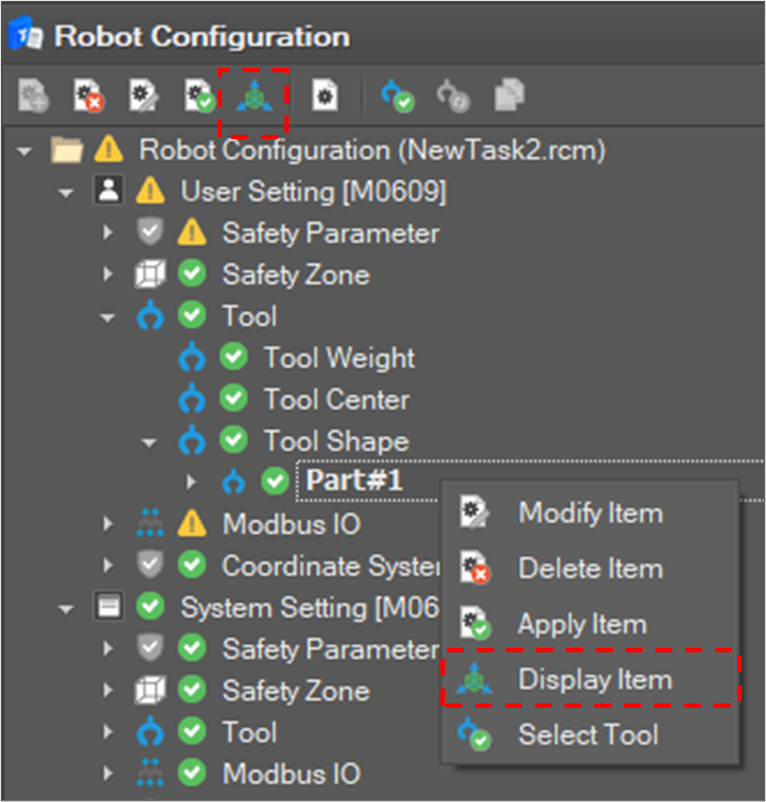
Then, the tool shape is displayed in the Motion Monitoring window.