IO Simulator
Even without a physical device connected, it is possible to perform an IO simulation of the GPIO and Modbus IO using a virtual controller. In the case of Modbus, it performs the Modbus Slave (Server) function and only supports TCP/IP.
Using the IO Simulator
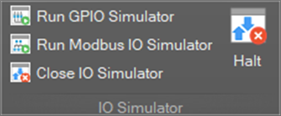
With a virtual controller connected, click the Run GPIO Simulator or Run Modbus IO Simulator from the Home -> IO Simulator group to open the simulator window and perform the IO simulator functions.
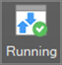
When the simulator window opens with a virtual controller connected, the IO simulator run status icon changes to Running.
Click the Close IO Simulator button to close the simulator window and end the simulation.
GPIO Simulation
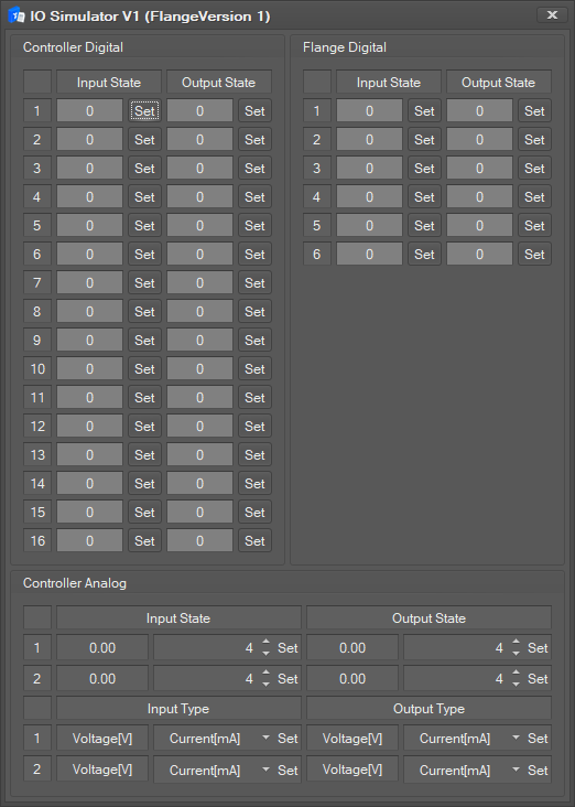
Click the Run GPIO Simulator button to open the simulator window as shown below.
- Flange Version 1
- Flange Version 2 (A Series)
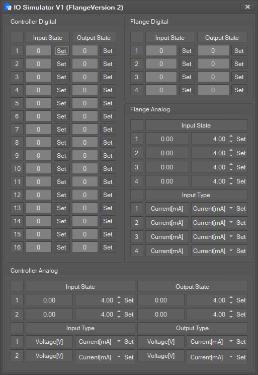
The digital IO status of the controller and flange are displayed.
- If the signal value is 1(true), the status field is displayed in green.
- If the signal value is 0(false), the status field is displayed in gray.
- To change the signal value, click the Set
The analog IO status and IO type of the controller and flange are displayed.
- Enter the signal value and press the Set button to set the value.
- Select the IO type and press the Set button to set the type.
- There are current type and voltage type.
- The voltage type will limit the signal value range to 0-10.
- The current type will limit the signal value range to 4-20.
Modbus IO Simulation
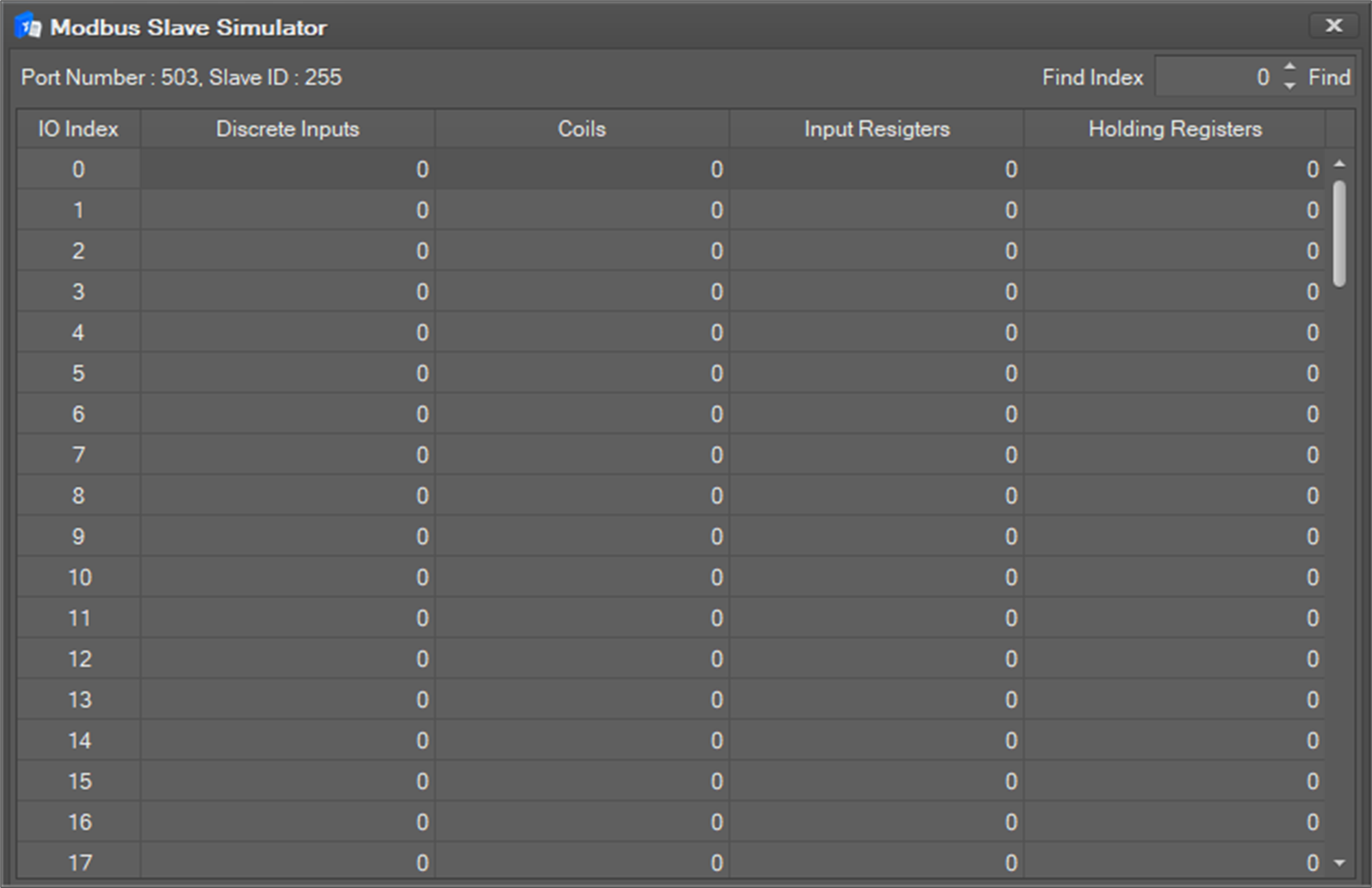
Click the Run Modbus IO Simulator button to open the simulator window as shown below.
Take caution of the fact that if more than 2 DART-Studio instances are running, only the first DART-Studio instance can run the Modbus IO Simulator, and the simulator cannot run in subsequent DART-Studio instances and the following log message will be displayed in the log window.

How to use the simulator:
- Add a Modbus IO to run the simulation in a robot environment. Refer to the Modbus IO for how to add a Modbus IO. Take note that only the TCP/IP Device is supported.
- When adding a Modbus IO, add it as a TCP device, and set the IP address as 127.0.0.1 (or the IP of the PC running DART-Studio), the port number as 503, the slave ID as 255, the desired IO type and index (0-100), and the initial value. In case of Multiple Holding Register and Multiple Coil, set the IO Start Index and Count instead of the index and initial value. Click the Confirm button (Apply Item) after setting to apply them to the virtual controller. It is also possible to simulate the Modbus IO applied on an actual controller, so add a Modbus IO using the IP of the actual controller. All other settings are identical.
- Change the cell value of the IO index set on the IO type column corresponding to the added Modbus IO and click the Set button as shown below to apply the changed values. The setting ranges for Discrete Inputs, Colis is 0-1, and for Input Registers, Holding Registers is 0-65535. In case of Discrete Inputs, Colis, 0 or 1 can be selected from the combo box type input window or can be entered with a direct key in of 0 or 1 after clicking the input window. Setting 0 or 1 with a toggle is also possible after double-clicking the input window.

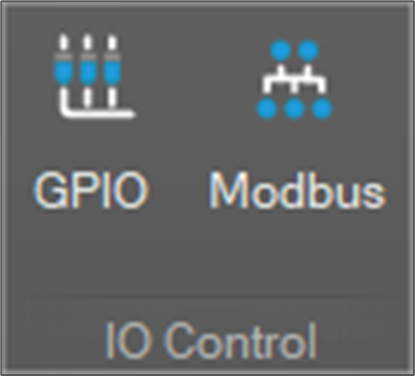
- It is also possible to monitor the value of the cell on the Modbus slave simulator window, as it applies the value changed from the Modbus IO Setting popup window displayed by clicking the Control -> IO Control -> Modbus button as shown below.
- Enter the index value (0-100) to search in the index input window of the Find Index on the top right and click the Find button to move the focus to the corresponding row.

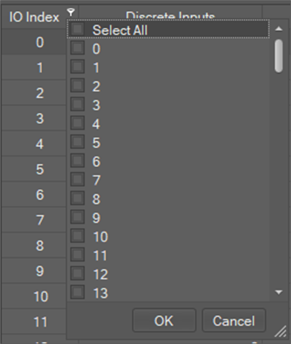
- Move the mouse cursor over the index column header to display filtering options as shown below. Select the checkbox of the items to display only the filtered items on the grid.