
Digital Welding Machine Configuration
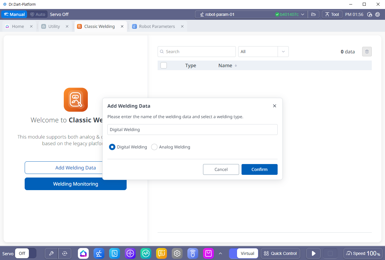
To use digital welding, click “Add Welding Data”, select “Digital Welding” and enter the welding machine name.
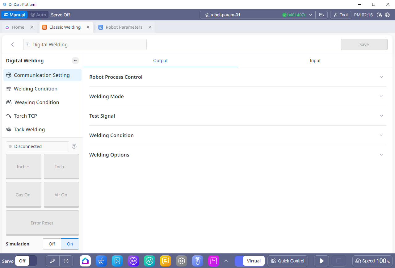
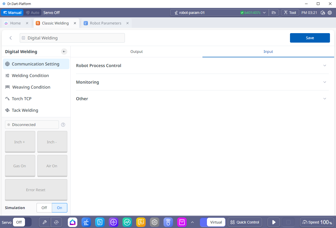
1. Communication Setting
Synergic welding machine and EtheNet/IP communication can be used to transmit and link bidirectional settings and signals between the robot and the welder. The functions provided by each welder and the signal setting information are different, and the ‘Welder Interface Setting’ menu allows you to set and use various welding conditions, linkage signals, and monitoring information provided by each welder through a universal UI.
The signals set and activated in the ‘Communication Settings’ menu are linked to related functions such as welding conditions and welding operation settings, so they must be set first. After completing the physical interface settings of the Arc Welding Overview, proceed with the settings in the ‘Communication Settings’ menu according to the description below.
No | Category | Desc |
|---|---|---|
1 | Output | Sets up the signals sent from the robot to the welding machine. |
2 | Input | Set up the signals sent from the welding machine to the robot. |
3 | Ethernet/IP Connect state | Displays the Ethernet/IP connection status between the robot and the welder. 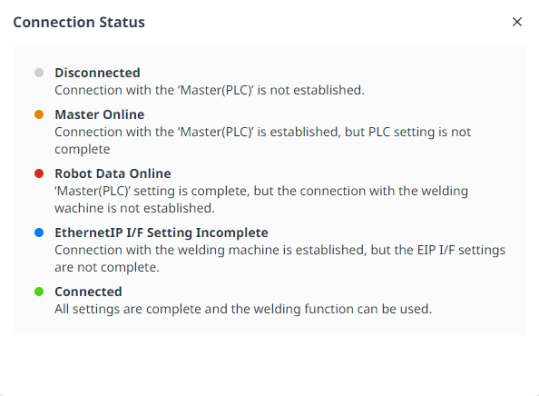 |
4 | Signal Test | Performs tests on the signals set based on the values set in the Interface Settings tab. 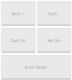 In the ‘Output’ tab, ‘Robot Process Control’ and ‘Test Signal’ items must be set for it to work. |
5 | Simulation | This is a menu where you can set the simulation when performing welding programming. If simulation is turned on, Arc will not operate.  |
For detailed explanation of the motion-welding linkage signals between robot and welder, please refer to the Motion-Welding Syncing Signals between Robot and Welder.
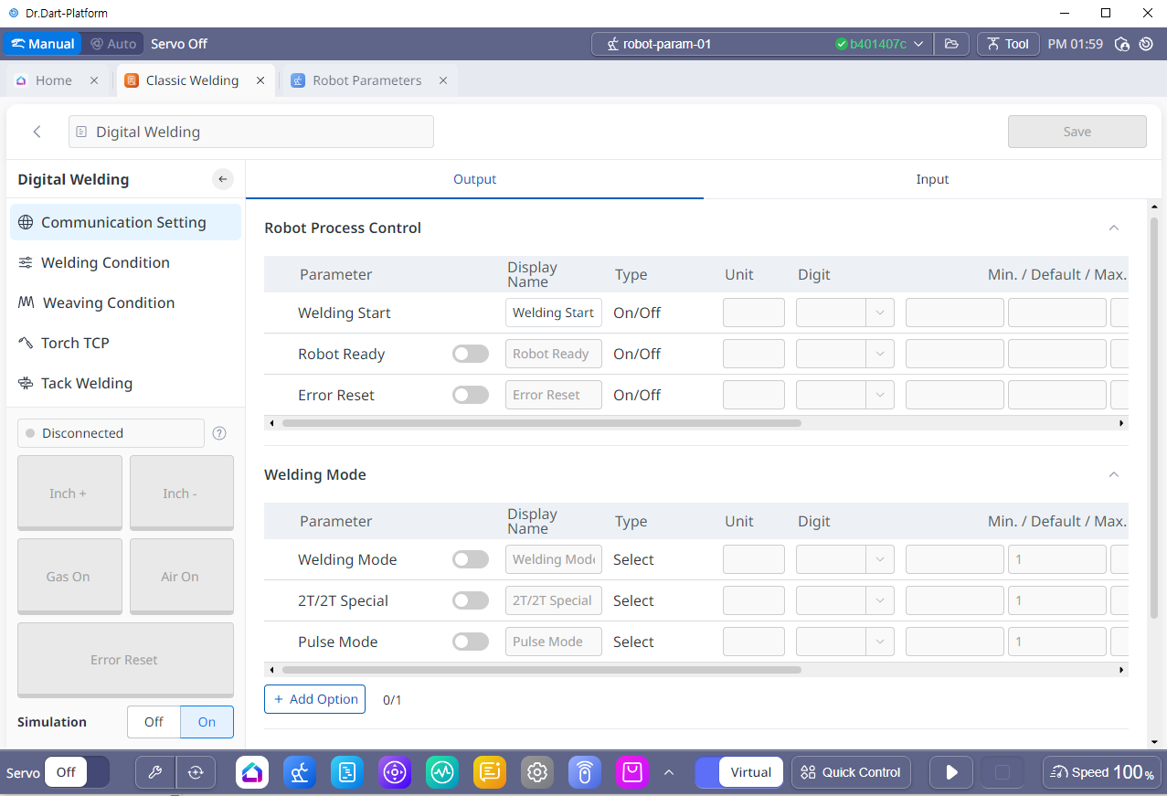
2. Output settings (setting signals from robot to welding machine)
Set the signals sent from the robot to the welder. The figure below shows the robot process control, welding mode, test signal, welding condition, and welding option signal settings.
No | Category | Desc |
|---|---|---|
1 | Robot Process Control | (Including required settings) Sets the signals transmitted from the robot to the welder for robot-welder linkage during welding. Includes Welding Start, Robot Ready, and Welder Error Reset signals. |
2 | Welding Mode | Sets the welding mode and operating mode signals, and can be used by setting the corresponding mode signal if provided by the welder. For detailed modes, please refer to the manual of the welder you wish to use.
|
3 | Test Signal | (Including required settings) Set for Wire Inching (+/-) (Inching +, Inching -), Gas Test, Air On, and Simulation signals. You can configure it by adding 2 more items as required. |
4 | Welding Condition | Select the synergic condition number and welding operation number stored in the welder and set the signals that can adjust the detailed conditions during welding. There are Job Number, Synergic ID, WFSpeed, Voltage Correction, and Dynamic Correction. |
5 | Welding Options | You can set it up by adding the necessary items. You can add up to 15. |
2-1. Robot Process Control
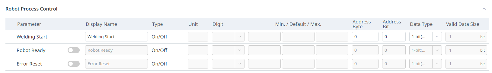
No | Category | Desc |
|---|---|---|
1 | Welding Start | Start welding operation |
2 | Robot Ready | Check robot ready |
3 | Error Reset | Includes a welding error reset signal. |
2-2. Welding Mode
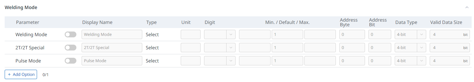
No | Category | Desc |
|---|---|---|
1 | Welding Mode | Specifies the welding mode settings specific to the welding machine. For example, it corresponds to the Working mode of the ‘Fronius’ welding machine. |
2 | 2T/2T Special | This is a signal to set the welding operation mode unique to the welding machine. It mainly specifies the welding start/end condition setting (2T/2T Special). For example, it corresponds to the operating mode (latched/non-latched mode) of the ‘EWM’ welding machine. |
3 | Pulse Mode | Specifies whether to use pulse welding mode. |
4 | Option | In addition to the basic mode designation items provided, you can use this when adding items that you want to change the mode. You can add option items by using the Add Option button at the bottom. |
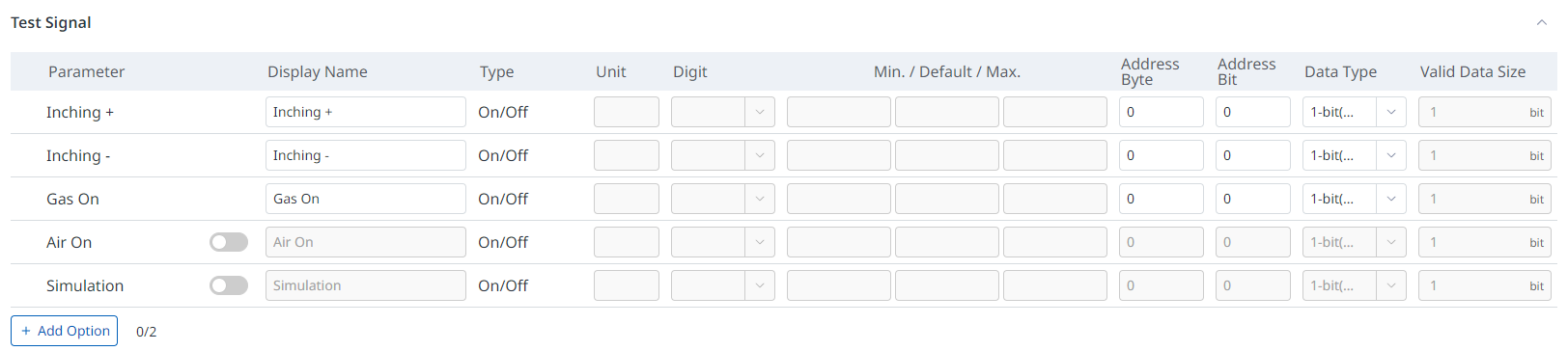
2-3. Test Signal
Set for Wire Inching (+/-) (Inching +, Inching -), Gas Test, Air On, and Simulation signals.
You can configure it by adding 2 more items as required.
2-4. Welding Condition
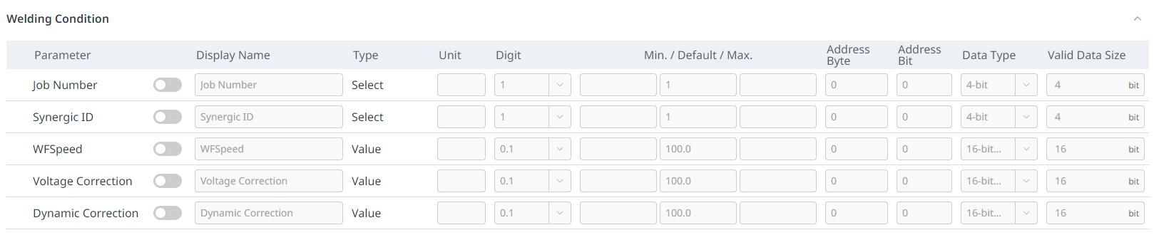
No | Category | Desc |
|---|---|---|
1 | Job Number | Specifies the job number value corresponding to the welding conditions stored in the welding machine. |
2 | Synergic ID | Specifies the program number value that stores the welding environment conditions for linking the synergy function provided by the welding machine. |
3 | WFSpeed | Specifies the wire feed speed value. |
4 | Voltage Correction | Specifies the voltage adjustment value during welding. |
5 | Dynamic Correction | Specifies the dynamic variable adjustment values for the welding machine during welding. |
2-5. Welding Options
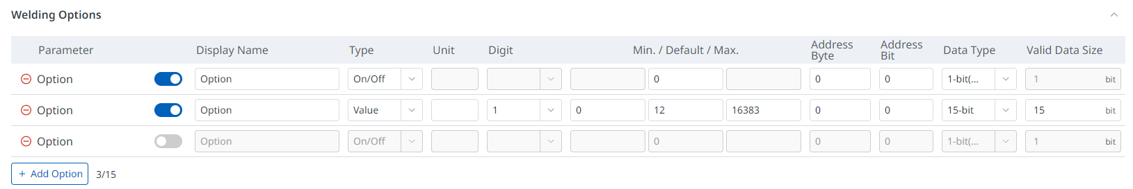
No | Category | Desc |
|---|---|---|
1 | Option | This can be used when you want to specify additional welding conditions in addition to the welding conditions provided by default. |
3. Input settings (setting signals from welding machine to robot)
Set up the signals sent from the welding machine to the robot. The figure below shows the robot process control, monitoring, and other signal settings.
No | Category | Desc |
|---|---|---|
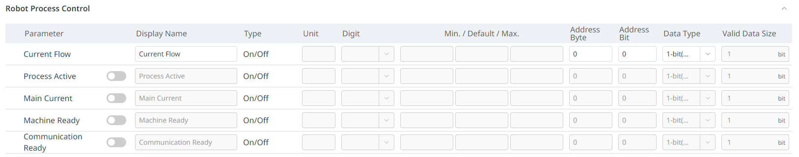
1 | Robot Process Control | (Including required settings) Sets the signal transmitted from the welder to the robot for linkage between the robot and welder during welding work. |
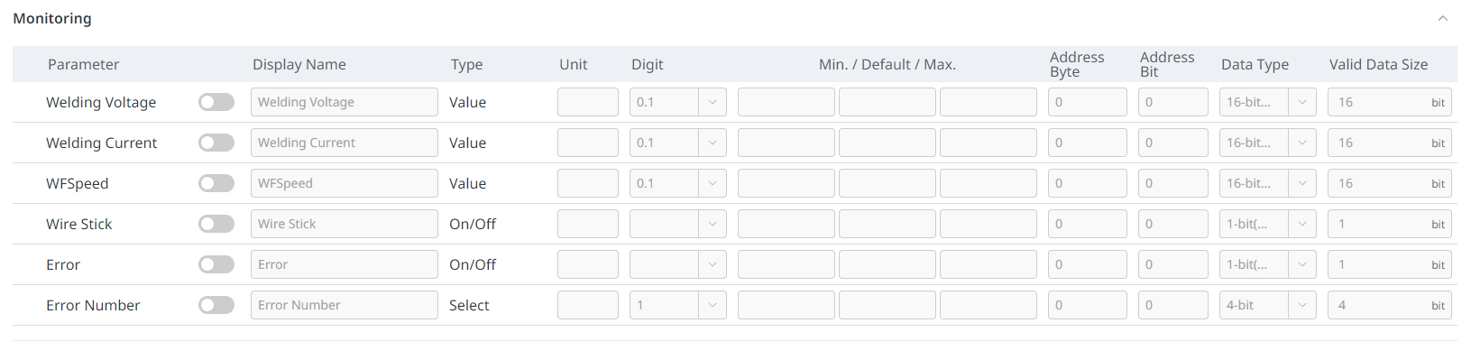
2 | Monitoring | Set the welding status information during welding, such as welding voltage, welding current, feed speed, wire stick, error, and error number. |
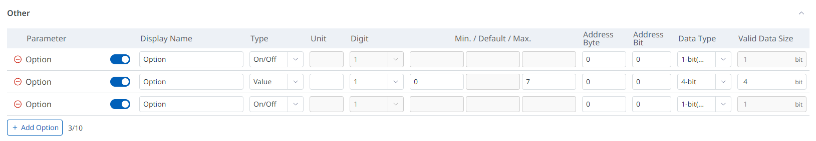
3 | Other | You can set it by adding the necessary items. You can add up to 10. |
3-1. Robot Process Control
3-2. Monitoring
3-3. Other
4. Signal Settings (Common)
You can pre-configure EtherNet/IP interface settings. The configured items are automatically configured and displayed when setting welding conditions.

You can set whether to use each item, display name, type, unit, number, minimum/default/maximum, address bytes, address bits, data type, and valid data size.
No | Category | Desc |
|---|---|---|
1 | Enable | Sets whether to use or not the item. Required settings for each group do not have a corresponding button. |
2 | Display name | Sets the name to be displayed when using the corresponding item in welding condition settings, etc. Since the names used for each welder are different, it is useful to enter the corresponding function name of the welding machine you want to connect to this item. Up to 20 characters can be entered in English. |
3 | Type | Sets the input method for the function.
|
4 | Unit | Sets the unit of the signal. |
5 | Digit | Sets the number of digits for the input value. (1 / 0.1 / 0.01) |
6 | Min/Default/Max | Set minimum/default/maximum values. |
7 | Address Byte | Sets the starting byte position of Data for communication. |
8 | Address Bit | Sets the starting bit position of Data for communication. |
9 | Data Type | Sets the size of the communication data. (1-bit(disable Low), 1-bit(disable High), 2-bit, 4-bit, 8-bit(byte), 15-bit, 16-bit(short), 32-bit(int)) |
10 | Valid Data Size | Set the size of the valid Data. You must enter a value within the type selected in ‘Data Type’ from 1. |
Info
For digital welding, after completing the settings, you must press the “Save” button in the upper right corner to set up communication with the welding machine.